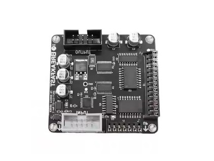
Audio PCB is a kind of printed circuit board specially used for audio equipment. It is responsible for carrying and connecting various electronic components in audio equipment, such as resistors, capacitors, transistors, integrated circuits, and so on.
The design and manufacture of Audio PCBs need to take into account the characteristics and requirements of audio signals, such as signal fidelity, noise suppression, interference protection, and other factors. At the same time, Audio PCBs also need to work with other audio equipment components to realize the amplification, filtering, mixing, and other functions of audio signals.
Precautions for Audio PCB design:
1. Microphone signal alignment should have a line width of 8mil or more.
2. Audioin and Audioout do not need to control the impedance,the alignment needs to be thickened to 15mil, the entire package of ground processing,and the interval of 300mil must play a ground over the hole.
3. SPDIF signal is recommended throughout the package ground processing,package ground alignment interval of 300mil or less must have a ground over the hole.
4. The headphone's left and right channel outputs should be wrapped independently to avoid crosstalk and optimize isolation, and it is recommended that the alignment width be greater than 10mil.
5. All CLK signals are recommended to be connected in series with 22ohm resistors and placed close to RK3588 to improve signal quality.
6. All CLK signals should not be next to each other to avoid crosstalk;clock signals need to be wrapped throughout the independent ground, wrapped within 300mil of the alignment interval must play a ground over the hole.
7. The decoupling capacitor of each IO power supply of the chip must be placed close to the chip. 8.
8. The audio interface is in accordance with the structure of the placement, there are no structural requirements as far as possible placed on the edge of the board, easy to plug and play.
9. IC placed near the interface, do not place too far, analog signals as short as possible.
10. Use differential signals: audio devices with differential inputs can suppress noise. Differential signals in the middle of the general can not be added to the ground (based on the application of the principle of differential signals the most important point is to take advantage of the mutual coupling between the differential signals to bring benefits, such as magnetic flux elimination, noise immunity, and so on. If you add a ground line in the middle will destroy the coupling effect).

11.ESD devices to be placed close to the audio interface, the alignment needs to ensure that the ESD device in the audio interface, does not punch a hole in the layer.
12.All audio signal lines should be routed away from inductive areas, away from RF signals and devices.
13.For an I2S interface connected to multiple devices, the relevant CLKs should be connected by the daisy-chained alignment topology; for a PDM interface connected to multiple devices, the relevant CLKs should be connected by the daisy-chained alignment topology; if there are enough GPIOs, both CLKs within a group of PDM interfaces can be used to optimize the alignment branching1.
All audio signals should be kept away from high-speed signal lines such as LCD and DRAM. It is prohibited to route in the adjacent layer of high-speed signal lines. The adjacent layer of audio signals must be a ground plane, and it is prohibited to punch a hole for layer change near high-speed signal lines.
14.Analog/digital ground split isolation: Basically, it is right to split the analog/digital ground isolation. But one thing to note is that the signal line tries not to cross the split place, and does not let the power and signal return current path change too much.
15.Speaker SPKP/SPKN signal coupling line, and the whole group of the ground package, line width according to the output of the peak current to calculate, and try to shorten the line to control the line resistance.
16.speaker's amplifier output if placed beads, LC filter, and other devices, it is recommended to be placed close to the amplifier output, can optimize the EMI.
17.Analog circuits use star grounding: audio power amplifiers generally consume a lot of current, which may have an adverse effect on their grounding or other reference grounding. However, it is possible to turn all unused areas of the board into grounding grounds. Ground coverage is implemented near the signal traces in order to shunt excess high-frequency energy from the signal lines to the earth via capacitive coupling.
18.When the microphone is connected single-ended, the MIC signals are routed separately and wrapped with the ground; when the microphone is connected differentially, especially in most cases of pseudo-differential, it should also be routed according to the differential and wrapped with the ground in the whole group.
19.Careful consideration of the ground plan: the ideal ground plan should divide different types of circuits in different areas.
20.For the headset base, microphone TVS protection diode, placed as close as possible to the connection base, the signal topology: headset base/microphone → TVS → IC; this makes the occurrence of ESD phenomenon, ESD current attenuation through the TVS device first; TVS device alignment does not have stumps, TVS ground pins are recommended to try to increase the ground over the hole, to ensure that at least two 0.4mm × 0.2mm over the hole, to strengthen the electrostatic discharge. Mm holes to strengthen the electrostatic discharge capacity.
Currently, Audio PCB recognized top-ranking audio product brands are: McIntosh, BOSE, ONKYO, Marantz, YAMAHA, Harman Kardon, etc., the development of audio products is a positive outlook, technological innovation, market demand growth, and high-speed network support will continue to promote the development of this field.