PCB circuit board edge high-frequency and high-speed signal lines of attention and high-frequency and high-speed signal design basic principles:
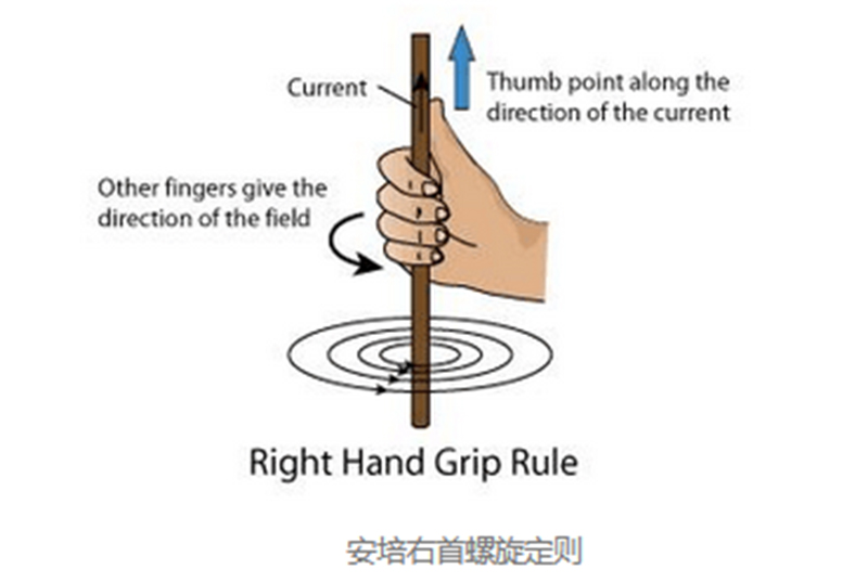
We have learned in the junior high school stage,with the right head on the wire stroking a fattening Ampere's right rule tells us that the wire contact current along the direction of the thumb widely spread, then the wire will be generated on the corresponding magnetic field, the direction of the magnetic field and the direction of the right head of the fingers of the fist in exactly the same direction, and the conductor in the electric charge will be generated by the electric field, the electric field and the magnetic field of a pair of good friends, collectively referred to as the electromagnetic force field.

According to Maxwell electromagnetic field theory,the change of the electric field in its surrounding space to produce the development of the change of the magnetic field, and the change of the magnetic field to produce the development of the change of the electric field. In this way, the change of the electric field and the change of the magnetic field rely on each other, mutual stimulation,alternately born,and with a certain speed from near and far in space widely spread out, this is electromagnetic radiation. This gives rise to two opposite effects: on the good side,all RF communication,wireless interconnection,and sensing applications are benefited from the benefits of electromagnetic radiation; while on the harmful side, electromagnetic radiation causes crosstalk and electromagnetic compatibility problems.
When the frequency of electromagnetic waves is low,they are transmitted mainly by the ability of tangible conductors; when the frequency grows gradually, the electromagnetic waves will spill out beyond the conductors, and it is not necessary for the medium to transmit energy at black ram,which is a kind of radiation. In low-frequency electric oscillations,the interaction between the magnetoelectricity and the electricity is not so rapid that almost all of the black ram is returned to the original circuit and no black ram is radiated out.However,in high-frequency electric oscillations,the magneto-electric interactions are so rapid that it is impossible for the black ram to return to the original oscillating circuits, and thus the electric energy and magnetic force are widely dispersed in space in the form of electromagnetic waves in accordance with the cyclic changes of the electric field and the magnetic field.
According to the above theory, every section of lead wire flowing through high frequency current will have electromagnetic radiation, and the intensity of radiation is directly proportional to the frequency. some lead wires on the PCB are used for signal transmission, such as the clock signal of the DDR chime, the LVDS differential signal transmission line, etc., so it is not expected that there are a lot of electromagnetic radiation to injure the black ram and cause interference to the other circuits in the system; and there are some leads used for the receiving antenna, such as In the case of some conductors used as receiving antennas, such as PCB receiving antennas, it is expected that the black ram can be converted into electromagnetic waves as much as possible.
For high-speed signal transmission lines on the PCB board (e.g. DDR chime clock signal, HDMI LVDS high-speed differential transmission lines), we always expect to try to reduce the radiation generated by the signal transmission lines, reduce the electromagnetic radiation generated by the signal transmission lines, a bricklayer has summarised the preset principles, such as to reduce the EMI of the signal transmission line, then try to get If the ratio of the width W of a signalised conveyor line to the distance H of the simplest surface of the simplest surface of the reference is less than 1:3, then the external radiation intensity of the microstrip conveyor line can be significantly reduced.
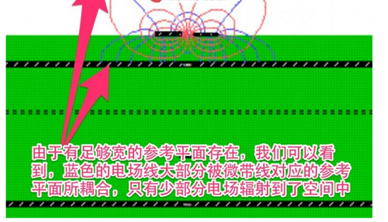
For microstrip conveyor lines, it is considered appropriate to use wide and complete reference to the simplest surface can also reduce the external radiation intensity of the electric field, microstrip conveyor lines corresponding to the reference to the simplest surface should be at least 3 times the width of the conveyor line, the wider the reference to the simplest surface, the better.

If the reference to the simplest surface is not wide enough with respect to the micro-monocoupler transmission line, the coupling of the electric field to the reference to the simplest surface is small, and the radiation from the electric field to the outside increases significantly.
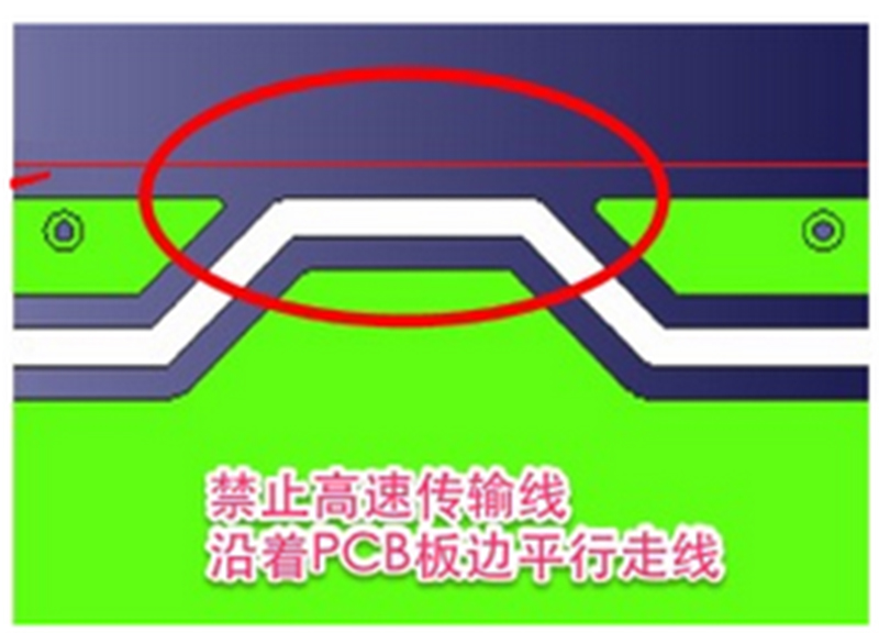
Therefore, if you want to reduce the height of the signal duct conveyor microstrip line of electromagnetic radiation,then the need for similar microstrip duct conveyor line corresponding to the reference to the simplest surface as much as possible, and if the high-speed microstrip duct conveyor line close to the edge of the circuit board to the parallel line,relatively speaking, the reference to the simplest surface of the high-speed signal line of coupling becomes less, naturally, good to lead to the electric field to the outside of a significant increase in radiation.

Similarly, high-speed ICs, crystals, etc. are also placed as far away from the edge of the board as possible, and high-speed ICs also require a complete and wide reference to the simplest surface of the implementation of electromagnetic coupling in order to reduce EMI.
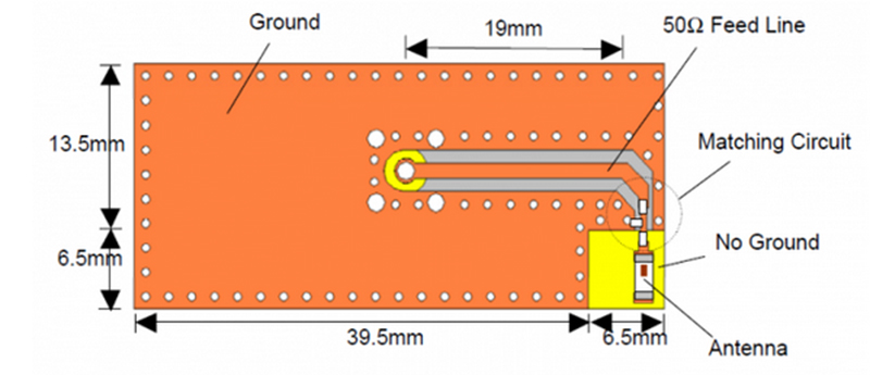
As for the board receiving antenna, we expect to radiate electromagnetic waves into the space as much as possible, so the default setting of the board receiving antenna is opposite to the default principle of the high-speed transmission line, the board receiving antenna needs to be placed at the edge of the board, and the receiving antenna area area should be strictly prohibited from the simplest surface of the copper foil, and all the layers need to be set up with the copper foil prohibited area. Also, the receiving antenna should be placed at a distance from the ground plane of the pcb board.

Abbey Circuits is a precision PCB manufacturer, specializing in the production of microwave circuit boards, Teflon high-frequency boards, Rogers boards, ceramic boards, HDI boards, FPC rigid-flexible PCBs, blind buried circuit boards, aluminium baseboards, thick copper circuit boards.