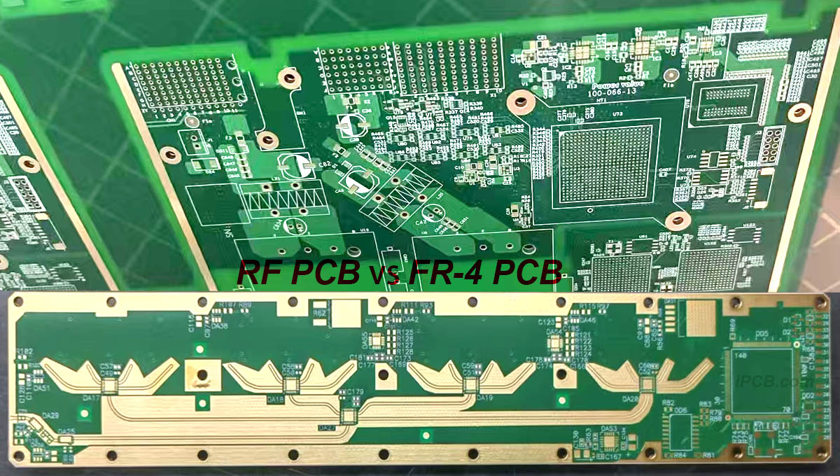
RF PCB refers specifically to PCB circuit boards with a frequency exceeding 1GHz. Although the precise definition in the industry may vary, this type of PCB has been widely used in cutting-edge fields such as communication systems, automotive ADAS (Advanced Driver Assistance Systems), satellite communications and radio systems due to its excellent physical properties, high precision and stringent technical indicators.
In addition to RF systems, modern devices also integrate digital processing and interface modules. With the growing demand for faster Internet access, mobile HD video streaming and Internet of Things (IoT) services, PCBs must not only meet high-frequency performance standards, but also support high-speed digital data transmission. Commercial applications such as IoT, 5G networks, big data centers, and increasing personal device applications continue to drive the speed requirements of digital communication systems. According to statistics, the rapid growth of data rates has caused the bandwidth of high-speed digital systems to double almost every three years.
The difference between RF PCB and conventional FR-4 PCB, although similar in production process, lies in the difference in material properties.The core material used in RF circuit board is copper-clad laminate designed for high-frequency and high-speed applications. This material has the characteristics of low dielectric constant (Dk) and low dielectric loss factor (Df), which is crucial to ensure the speed and quality of signal transmission.

RF PCB
RF circuit board vs FR-4 PCB dielectric constant (Dk) comparison
1.RF PCB requires the substrate to have a stable and low dielectric constant, because the propagation speed of the signal is inversely proportional to the square root of the dielectric constant of the material, and a high dielectric constant will cause signal delay.
2. In contrast, conventional FR-4 PCB has a looser requirement for dielectric constant, mainly to meet basic circuit connection requirements.
RF PCB vs FR-4 PCB dielectric loss factor (Df) comparison
1. RF PCB requires the substrate to have extremely low dielectric loss to reduce attenuation and heat accumulation during signal transmission.
2. Conventional FR-4 PCB has relatively low requirements in this regard.
Impedance characteristics of RF PCB vs FR-4 PCB
1. Impedance control is one of the basic principles of high-speed design, and RF PCB has strict regulations on this to ensure the stability and integrity of signal transmission.
2. Conventional FR-4 PCBs are usually more flexible in terms of impedance control.
Comparison of water absorption of RF circuit board vs FR-4 PCB
1. RF PCB requires low water absorption of the substrate to prevent changes in dielectric constant and dielectric loss due to moisture.
2. Conventional FR-4 PCB has more relaxed requirements in this regard.
Material properties of RF circuit board: The core focus is on the values of dielectric constant (Dk) and dielectric loss factor (Df) and their consistency and stability. These parameters are crucial to ensure the quality and efficiency of signal transmission.
Application scenarios: RF circuit boards are widely used in communication systems, automotive ADAS (advanced driver assistance systems), satellite communications and other fields to meet the growing demand for high-frequency and high-speed signal transmission.
Material properties of high speed: Mainly focus on the optimization of dielectric loss (Df). Commonly used high-speed materials in the market are divided into different grades according to the size of dielectric loss to meet the needs of different applications.
RF circuit board not only focuses on the stability and variation range of dielectric constant (Dk), but also attaches importance to key indicators such as material dielectric thickness, temperature drift coefficient and stroboscopic performance. RF PCB materials are mainly divided into polytetrafluoroethylene (PTFE) and non-PTFE types. The appropriate material type is selected according to the specific application field.
Polyphenylene ether (PPO or PPE) material: It has attracted much attention in recent years. Its dielectric properties are second only to PTFE, and its processing performance is better. In the applications of very low loss (Very Low Loss) and ultra low loss (Ultra Low Loss) in high-speed boards, modified PPO resins such as Panasonic M6, M7N and Lianmao's IT968, IT988GSE have become the mainstream choice.
RF PCB solution: Although PTFE and PCH materials perform well in dielectric loss (Df) and dielectric constant (Dk), their processing performance limits their application in high-layer boards and HDI boards. To solve this problem, material developers use modified PPO resin to make high-frequency boards, such as the high-frequency boards such as IT-88GMW, IT-8300GA, IT-8350G, IT-8338G, and IT-8615G launched by Lianmao. By mixing modified PPO resin and hydrocarbon resin, it not only meets the needs of high-frequency signal transmission, but also greatly improves the processability of the material.
Future development trend of RF PCB: With the continuous evolution of 5G communication technology, high-frequency products have increasingly stringent requirements for PCB. High-frequency signal transmission requires lower dielectric loss (Df) and more stable dielectric constant (Dk). At the same time, the trend of product miniaturization and unification promotes the development of PCB towards high-layer and HDI, which puts higher requirements on the processability of materials. Therefore, polyphenylene ether (PPO or PPE) resin shows good development prospects due to its excellent dielectric properties and processing performance, and will become an important development direction of RF circuit board in the future.