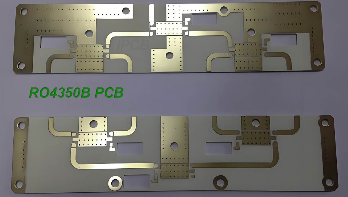
As a high-frequency PCB material under the Rogers brand, RO4350B PCB has excellent DK stability. In the standard test, the DK value measured at 10GHz is 3.48, and this value decreases as the frequency increases. For example, at 24GHz, DK drops by 0.01 to 3.47 compared to 10GHz.
When selecting high-frequency PCB materials, we usually need to consider the following key factors: DK, DF, frequency and temperature stability, and overall cost (including material cost, design, testing and manufacturing cost). The RO4350B PCB material launched by Rogers combines hydrocarbon resin with ceramic filler laminates and prepregs to form a low DF material. This material performs well in high-frequency performance and is generally suitable for scenarios below 30GHz.
It is worth mentioning that the RO4350B PCB uses a standard epoxy resin/glass (ie FR-4 fiberglass board) processing technology, and its circuit processing cost is relatively low. This makes RO4350B PCB reach an ideal balance between cost and high-frequency performance, becoming one of the most cost-effective low-DF high-frequency PCB materials on the market. In order to meet more sophisticated design requirements, I specially studied the insertion loss of microstrip transmission lines based on RO4350B PCB materials at 24GHz frequency during the design of microstrip array antennas. Through this study, we hope to better play the performance advantages of RO4350B PCB materials and provide more reliable solutions for the design and application of high-frequency circuits.

RO4350B PCB
The insertion loss of microstrip lines mainly includes conductor loss, dielectric loss, surface wave loss and radiation loss, among which conductor loss and dielectric loss dominate. The distribution of high-frequency current on the microstrip line is affected by the skin effect, so that the current is mainly concentrated in the thin layer between the conduction strip, the ground plane and the dielectric substrate. Therefore, the equivalent AC resistance at high frequency is much greater than that at low frequency. At operating frequencies below 10GHz, the conductor loss of microstrip lines is significantly greater than the dielectric loss. However, when the operating frequency climbs to 24GHz, the dielectric loss begins to surpass the conductor loss and becomes the dominant factor.
Strategies to reduce microstrip line insertion loss
1. Carefully select the thickness of the high-frequency circuit board and use green oil with caution
Under the condition of the same characteristic impedance, the conductor loss of the microstrip line will show a decreasing trend with the increase of the dielectric thickness, while the dielectric loss will remain basically stable. The reason behind this is that as the thickness of the dielectric base increases, the width of the microstrip line will become narrower accordingly, resulting in more concentrated high-frequency current, which in turn increases the conductor loss.
In addition, at a frequency of 24GHz, the loss tangent of the green oil medium is large, which will further increase the insertion loss of the microstrip line. Therefore, when designing a 24GHz microstrip antenna, we need to perform solder mask window treatment on the antenna area to reduce the adverse effects of green oil on the insertion loss of the microstrip line.
2. Choose high-quality LoPro copper foil
In the design of microstrip lines, the surface roughness of the copper foil of the conductor and ground plane cannot be ignored. Generally speaking, the smoother the copper foil surface, the smaller the conductor loss. Therefore, choosing a copper foil with lower surface roughness is the key to reducing the insertion loss of microstrip lines.
Rogers RO4350B PCB provides two types of copper cladding, namely electrolytic copper foil (ED) and low roughness reverse copper foil (LoPro). Among the two, the surface roughness of ED copper foil is about 3um, while LoPro copper foil can reach an ultra-low roughness of 0.4um. This low roughness characteristic makes LoPro copper foil perform well in reducing conductor loss.
For example, at a frequency of 24GHz, the insertion loss of microstrip lines using LoPro copper foil is 40% lower than that using ED copper foil. This data fully demonstrates the advantages of LoPro copper foil in reducing microstrip line insertion loss.
3. Carefully select PCB surface treatment process
In microstrip line design, the choice of PCB surface treatment process also has a significant impact on conductor loss. At present, common surface treatment processes mainly include immersion silver, immersion gold (nickel-free gold), nickel gold (nickel 3-5um, gold 2.54-7.62um) and immersion tin. The metals used in these different processes have their own unique electrical parameters, which directly affect the size of conductor loss.
Nickel is particularly worth mentioning. As a ferromagnetic material, its magnetic DK is as high as 600. According to the calculation formula of skin depth, the skin depth of nickel is one order of magnitude smaller than that of other metals. This means that when high-frequency current passes through, the surface resistance of nickel will be dozens of times greater than that of other metals, so the conductor loss of the nickel-gold process will also be much greater than that of other processes.
The insertion loss of the silver immersion process and bare copper is not much different, but the insertion loss of the microstrip line after nickel-gold surface treatment is 4dB/m greater (at 10GHz). It can be predicted that as the frequency increases, this difference will further increase at 24GHz. When we use Rogers RO4350B PCB material to design microstrip antennas or microstrip circuits for the 24GHz frequency band, we must comprehensively consider the thickness of the dielectric board, the type of copper cladding, and the surface treatment process to ensure that while meeting performance requirements, we also achieve cost optimization.