PCB antenna is a type of wire printed on a PCB board, which has the advantages of small size, simple structure, and convenient manufacturing. Therefore, it is widely
used in wireless communication and RF systems. With the development of technologies such as the Internet of Things, smart homes, and wireless sensor networks,
the demand for smaller and higher performance PCB antennas is gradually increasing. Therefore, the analysis and application design of PCB antennas have important
research value.
Designing antennas into wireless embedded or IoT devices requires special care to maximize performance.
When designing wireless devices, it is important to pay attention to the antenna layout on the PCB. The space, position, gap, grounding layer, and correct connection
with other components on the PCB can all affect the performance of the antenna. Properly considering these aspects from the initial design concept will help achieve
successful transmission and reliable wireless performance.
Antenna placement:
Due to the sensitivity of the antenna to the surrounding environment, the approximate position of the antenna within the device may have an impact on the design.
Please place the antenna in a location that can protect it from objects that may cause electrical interference to the antenna
The casing of the device can affect the performance of the antenna. If the casing is made of metal or fiberglass filled plastic, it will also suppress the radiation energy
of the antenna. Unless using a special antenna, please consider using non glass fiber filled plastic to make the casing.
Antennas are usually designed to work in corner positions, but some antennas work best on the long or short sides of the PCB. Some antennas come in two versions:
left and right. You can choose the antenna that is most suitable for PCB design and layout

PCB antenna design
The position of the antenna relative to other components
Even high-performance and efficient antennas cannot function properly when in close proximity to other interfering components. This interference may come from
a component on the PCB or other objects near the antenna.
Some components can cause interference to the signal radiated by the antenna. Battery LCD、 Motors and other metal objects may generate noise or reflections,
which can interfere with the performance of the antenna. Therefore, the antenna should be kept as far away from these objects as possible
Check the length requirements of the grounding plane:
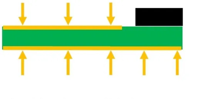
Surface mount device (SMD) antennas typically require a ground plane to radiate energy. The grounding plane is a plane that functions somewhat like a mirror, balancing
the reciprocity of the antenna.
The grounding plane is usually longer than the antenna. Its length depends on the minimum operating frequency. The data manual will specify the requirements for
the grounding plane, but this also means that you need to leave a restricted area below the antenna. If the space is limited, we recommend choosing an antenna that
requires a very small ground plane to meet the efficiency requirements of carrier radiation standards.
PCB antennas are widely used in fields such as wireless communication, wireless sensor networks, and the Internet of Things. According to different application requirements,
appropriate P (B) antenna design and optimization are needed, such as adjusting parameters such as gain, size, and bandwidth. Meanwhile, the performance of PCB antennas
can be further optimized through methods such as antenna arrays, multi band design, and polarization adjustment.
PCB antenna design is a comprehensive task that requires consideration of principles, parameters, processes, and application scenarios. By deeply understanding the design
elements, strictly following the design process, flexibly applying optimization strategies, and adjusting for different scenarios, high-performance PCB antennas that meet the
requirements can be designed.