O-RAN Introduction
Today, the use of cellular materials continues to grow globally, so telecoms systems must be revolutionised to meet this demand. While the 5G standard is capable of meeting the demand for higher cellular traffic and promises to enable a variety of new application scenarios, many of the proposed 5G applications will only be possible on paper if the network is not improved accordingly. Ultra-reliable, low-latency communications (URLLC) application scenarios, for example, will not be possible without network optimisation due to the high latency requirements of such applications. The network of the future will need to become more flexible and be able to take advantage of new technologies such as artificial intelligence. Network operators are moving to software-defined networks to be able to customise and manage their deployments.
Mobile network operators will also need to enable device interoperability,or the ability to freely choose network equipment electronic components from different vendors. Overall, there is a lot of room for improvement in both the radio access network (RAN) and the telecommunications system hardware.3GPP R15 identifies three different gNodeB functions:the central unit (CU), the distributed unit (DU) and the radio unit (RU).These three elements can be configured in a variety of ways,and it is best to determine the best configuration for your respective network.If the gNodeB components are all from the same vendor,then a dedicated interface can be selected between these components.
The O-RAN Alliance,or O-RAN,is committed to driving unprecedented openness in 5G RANs.The O-RAN Alliance charter describes how open CU,DU and RU interfaces can enable white-boxed networks, where the functionality of the entire system is not completely vendor-defined, thus increasing the flexibility of RANs and providing more choice for network operators.Moreover,this approach can bring new opportunities to SMEs that traditionally do not provide network hardware, encouraging them to innovate and develop.The more innovations,the more choices,meaning the cost of deploying a new network is likely to be lower. o-RAN also wants to integrate deep learning technologies into every RAN architecture, thereby increasing the intelligence of the communication system. o-RAN's reference architecture (shown in Figure 1) illustrates how to build a RAN that is compatible with O-RAN.
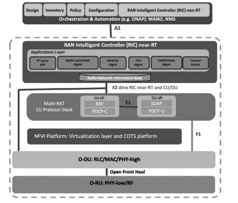
Figure 1. O-RAN Alliance Reference Architecture
How to slice the RAN
The concept and architecture of O-RAN is based on the concept of RAN slicing. Functionally, there are eight ways to slice the RAN, each of which slices different protocol layers so that different parts of the protocol stack can be processed on different hardware. Figure 2 summarises these eight options.

Figure 2. RAN Slicing Options
O-RAN recommends the use of Option 7-2. As shown in Figure 2,this option slices the physical layer (PHY) into high and low layers. If option 7-2 is used, in the uplink (UL), the CP removal, Fast Fourier Transform (FFT), digital beamforming (if applicable) and pre-filtering (only for PRACH (Physical Random Access Channel)) functions are carried out in the RU, while the rest of the processing in the physical layer is performed in the DU. In the downlink (DL), the inverse FFT (iFFT), CP add, pre-coding functions and digital beamforming (if applicable) are performed in the RU, while the rest of the PHY processing is performed in the DU.
Option 8 slice follows the Common Public Radio Interface (CPRI) used for 2G, 3G and 4G.O-RAN specifies a version of the 7-2 cut that reduces the traffic between the DU and the RUs.Figure 3 below explains the 7-2 slice option and how the rest of the protocol stack can be sliced between CUs and DUs.7.2x slice strikes an optimal balance between bringing the technology to market quickly and controlling the cost of deployment.This approach reduces confusion about the details of the slice, while further reducing traffic and improving quality. Some 5G systems use evolved CPRI, or eCPRI, as the DU-RU interface.ECPRI allows for vendor-specific high- and low-level slicing of the physical layer. Thus, by supporting multiple slices, traffic or flexibility can be optimised to adapt to different deployment environments due to unique antenna physical environments. This enables cost optimisation for specific connections for different operators.
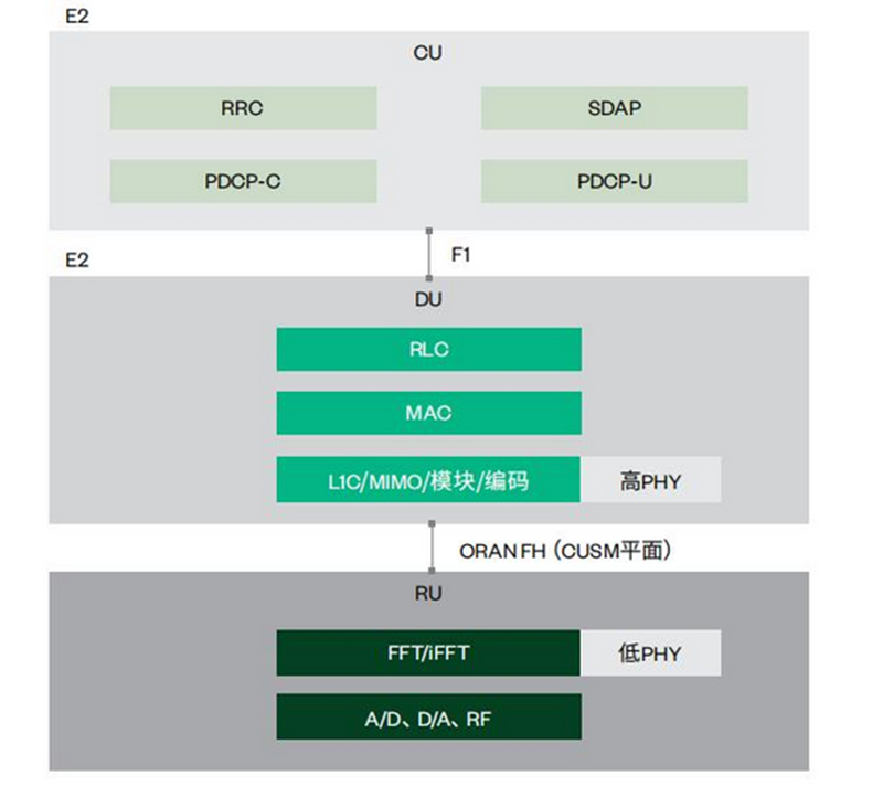
Figure 3. CU, DU, and RU Protocol Layer Slicing for Option 7-2
For the new 5G RAN architecture (called NR-RAN), 3GPP has defined and standardised a new F1 interface for communication between CUs and DUs. the physical slice between CUs and DUs is called high level slice (HLS). the lower level interface between DUs and RUs is called low level slice (LLS), which is not yet defined by 3GPP. the relationship between CUs and DUs, and their relationship with RUs, can be configured in various ways. The relationship between CUs and DUs, as well as their relationship with RUs, can be configured in various ways. Figure 4 shows the different NR-RAN configurations.Note that the F1 interface is delay tolerant while the DU-RU interface requires low latency transmission. Thus, there are many challenges in creating low-latency interfaces, so in the second half of this paper, we present a detailed low-level slicing application scenario for central RAN.
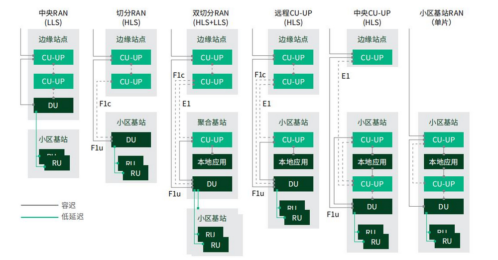
Figure 4. Flexible 5G RAN Functional Unit Locations
The interface between the DU and the RU is also known as the fronthaul (FH) interface.The FH interface is one of the most demanding system interfaces and is very sensitive to delay. If the DU and RU are supplied by the same manufacturer, most systems can use CPRI or eCPRI (5G only) as the fronthaul interface.Although CPRI was originally designed to be used as an open interface, in practice, each vendor has a slightly different implementation to match its own hardware, making multi-vendor interoperability difficult,if not impractical.While open white box hardware architectures are discouraged, tight synchronisation between DUs and RUs can be achieved more easily. If the DUs and RUs are supplied by the same vendor, they will match in terms of transmit time and receive time (the only variation is the distance between the DUs and RUs).
One of the two goals of O-RAN is to create a more open ecosystem, which requires the definition of a new forwarding interface. Of the seven O-RAN working groups, Working Group 4 (WG4) is dedicated to defining this interface. This WG is called the Open Forward Interface WG and its goal is ‘to provide a truly open forward interface to enable multi-vendor DU-RRU interoperation.’ Figure 5 shows how the proposed DU-RU interface exchanges information across different planes. Whilst these seven different flows (plus additional Management (M) plane flows) may seem very complex, at a higher level, the four planes (Control, User, Synchronisation and Management) actually use only three material types (IQ material, Timing and Synchronisation material, Command and Control information).
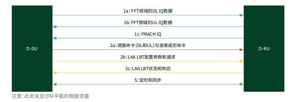
Fig. 5. Flow of low-level forward material
Since CPRI is based on the Option 8 slicing method, the forward interface is very different from CPRI in terms of how the IQ material is transmitted, packetised and de-compressed. Option 8 can slice the network at the RF layer, so the IQ samples are not subjected to any PHY processing (FFT/iFFT). As networks evolve in the late 4G and early 5G phases, with more antennas being used in Massive Multiple Input Multiple Output (MIMO), and the sampling rate (multiple samples per antenna) increasing, eCPRI was created to reduce the amount of material flow through the interface. Since the amount of system material is beyond the capacity of the physical connection and it would be too expensive to implement a connection that can accommodate that amount of material, eCPRI moves a portion of the material from the PHY to the RU and adds a compression algorithm in order to reduce the amount of material that passes through the interface.
However, there is no specific cut-off criteria for exactly which parts of the PHY are to be moved into the RU, and this varies from supplier to supplier. For some providers this may be a competitive advantage, and this approach may help the operator to reduce link costs. As some of the low-level PHY functions are performed in the RU, the DU needs to inform the RU how to perform these functions. As a result, the command and control interface of eCPRI is also quite different from that of O-RAN's pre-transmission interface. However the different cuts of each of the providers will result in the service provider continuing to be dependent on the vendor. the open forward interface of O-RAN aims to establish a corresponding standard for the parts of the physical layer that need to be moved into the RUs for the integration of hardware provided by different vendors through the use of a 7-2x cut.
Interoperability Testing (IOT)
Whilst working to improve the front-end interface, WG4 must also consider how the interface will be tested. If the system contains DUs and RUs from different hardware vendors, system integrators and vendors will be required to have appropriate DU and RU interface validation capabilities. This type of testing is often referred to as interoperability testing, and O-RAN is investigating how to test systems that are compatible with O-RAN. The O-RAN sketch shown in Figure 6 illustrates a system configuration for testing O-RAN-DUs (O-DUs) and O-RAN-RUs (O-RUs) using O-RAN-CUs (O-CUs) and UEs, in a configuration that can be used for laboratory simulation or commercially available. One test point is used to test the interface between the CU and the DU, and another test point is used to test the RU RF inputs/outputs, but the device under test (DUT) is a combination of the DU and the RU. In this case, if active excitation is used, the pre-transmission interface between the DU and RU is not tested and the test is only possible with passive monitoring.O-RAN is currently investigating how to test the pre-transmission interface.
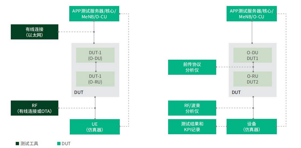
Fig. 6. O-RAN test setup, active (left) and passive (right)
There are two types of active tests that can be performed on the forward interface:protocol tests and parametric tests,and O-RAN has demonstrated the need for protocol tests for test case validation and failure analysis. During the development process, it is important to have test tools that can validate the design to ensure proper connection to other O-RAN-compatible devices. Once the design is complete and the DUs and RUs are in the verification and production stages, parametric testing is required to ensure that each unit is functioning as expected.
For the RU test system, the E1 interface between the CU and the DU does not need to be tested; the RU test system must be capable of analogous functionality to that of the CU and DU and be able to monitor the forward interface. Depending on the level of testing required, test UEs or UE emulators can be added to the system to build a complete end-to-end (E2E) test system. 5G NR IP based on NI's software radio (SDR) and FPGA hardware is available. an example of an E2E test system is shown in Figure 7 below.

Figure 7. E2E DU-RU Test System Example
Conclusion
O-RAN formulates three visions:
(1) Create a smarter RAN network and maximise efficiency through virtualisation of network elements.
(2) Promote hardware white-boxing to realise multi-vendor network solutions.
(3) Standardise network component interfaces
O-RAN's goal in implementing these key initiatives is to drive network development that is better suited to future needs and to integrate new features and application scenarios that are expected to be enabled by 5G,such as URLLC. The definition of the forward interface is particularly challenging due to the low-latency transmission required for DU-RU communication, which is an area where O-RAN Working Group 4 continues to make progress and where companies have already begun to build RUs that are compatible with O-RAN. O-RAN Working Group 4 continues to make progress in this area, and several companies have begun constructing O-RAN-compatible RUs that can be used to connect to other O-RAN-compatible hardware.
As this new technology comes to market,the ability to validate and test the DU-RU interface is critical, both during the design and validation phase as well as during production testing, and NI offers IOT test hardware and software that will enable companies to bring new O-RAN-compatible RUs to market more quickly.It is unclear whether O-RAN will be widely adopted and used in 5G networks; however, the O-RAN consortium is actively defining new interfaces and working on ways to optimise and advance the network by building new networks with multi-vendor hardware solutions.