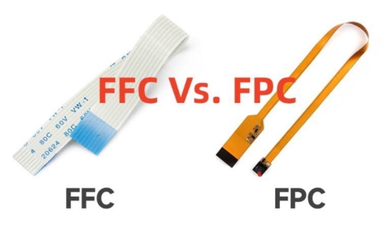
In modern electronics design, the demand for flexible, space-saving interconnect solutions continues to grow. Flexible Flat Cables (FFC) and Flexible Printed Circuits (FPC) have become essential elements in applications ranging from smartphones and laptops to automotive infotainment and industrial control panels. While FFCs and FPCs share similarities in providing flexibility and compact form factors, their respective connectors require careful selection and integration to ensure mechanical reliability and electrical performance.
This article provides a clear, practical look at how FFC and FPC connectors differ, where each is best used, and critical design considerations you should know before choosing one for your project.
1. Understanding FFC and FPC: Not the Same Thing
FFC (Flexible Flat Cable) is a simple ribbon-like cable made of parallel flat conductors laminated between insulating films. It typically comes in standard pitches — common examples include 0.5mm, 1.0mm, and 1.25mm — and is prized for its low cost and ease of assembly. FFCs are mass-produced and widely used for board-to-board connections in consumer electronics like printers, scanners, and displays.
FPC (Flexible Printed Circuit), on the other hand, is an actual printed circuit board (PCB) made on a flexible substrate, usually polyimide. It can have single, double, or multiple copper layers with etched traces, vias, pads, and sometimes embedded components. This makes FPCs highly customizable for complex designs with more routing options, controlled impedance traces, and tighter bend radii.
2. FFC vs FPC Connectors: What’s Different?
Although many catalogues refer to them interchangeably, FFC and FPC connectors can have different mechanical features:
Contact Style:
Most FFC/FPC connectors use Zero Insertion Force (ZIF) or Low Insertion Force (LIF) contacts. These connectors include a locking actuator or slider that holds the cable securely, minimizing stress during mating/unmating. FPC connectors often have better alignment features or stiffer contacts to accommodate the added thickness and pad features of FPC tails.
Stiffener Compatibility:
FPCs typically require a stiffener at the connector tail to provide rigidity and a consistent thickness for reliable contact engagement. Many FFCs, being inherently uniform, do not need this.
Pitch Tolerance:
FFC connectors assume uniform conductor pitch and thickness. In contrast, FPC connectors may tolerate slight variances in tail thickness or include guides to ensure correct positioning, especially for multilayer designs.
Retention Force:
FPC connectors may use stronger latches or double contacts for applications that face vibration or repeated flexing. In contrast, low-cost FFC connectors might have simpler latch designs.
EMI Shielding:
Higher-end FPC connectors sometimes include ground pins or shielding to handle high-speed differential signals, while FFCs are mostly for lower-frequency applications.

3. Choosing Between FFC and FPC Connectors
The right choice depends on a mix of cost, signal integrity, assembly, and mechanical stress factors:
Cost and Simplicity:
If your design only needs simple point-to-point connections with no routing or embedded passives, FFC plus an FFC connector is the easiest, most economical solution.
Signal Density and Routing:
For complex designs where space constraints and signal integrity matter — for example, in foldable devices, cameras, or RF modules — FPCs allow more intricate layouts and controlled impedance traces, but require precision connectors that maintain consistent contact under bending.
Mechanical Reliability:
Consider the number of insertion cycles. If the connector will be mated and unmated frequently, a ZIF connector is essential to prevent contact wear and damage.
Environment and Vibration:
If the cable will flex constantly or face vibration, reinforced FPC connectors with strain relief features will extend the lifespan of the connection.
4. Practical Design Tips for FFC/FPC Connectors
Here are some field-proven practices to ensure your FFC/FPC connections are robust:
Specify the Annular Ring and Pad Size Clearly
For FPC designs with vias, maintain adequate annular ring width (typically ≥5 mils) to prevent breakout during fabrication.
Add Stiffeners for FPC Tails
A good stiffener not only ensures reliable insertion but also acts as a strain relief zone. Polyimide or FR4 stiffeners are common choices.
Control Bending Radius
Avoid sharp bends at the connector entry. For polyimide FPCs, the minimum bend radius is generally 6-10 times the thickness. Bending too close to the contact area can stress solder joints.
Check Insertion Direction and Locking Mechanism
ZIF connectors can be top-entry or side-entry. Double-check the mating direction in your design files to prevent reverse insertion or mechanical interference inside the enclosure.
Clean Handling and Storage
Fingerprints or debris on FPC tail pads can cause contact resistance. Always handle with gloves in ESD-safe environments. Store FFC/FPCs flat to avoid unwanted creases.
Perform Insertion/Withdrawal Tests
If your product will be serviced frequently, test the durability of the connector latch and contacts through multiple mating cycles. Check retention force against the manufacturer’s spec.
5. Common Pitfalls to Avoid
Assuming All FFC/FPC Connectors Are Interchangeable:
Always verify the actual cable thickness, stiffener height, and pitch. A mismatch can lead to poor contact or latch failure.
Ignoring Signal Integrity:
For high-speed signals, use differential pair routing on FPCs and match connector impedance. Adding ground contacts can reduce crosstalk.
Underestimating Assembly Tolerance:
Small misalignments during manual insertion can bend contacts. Use guide rails or jigs if your assembly line is manual.
Conclusion
As electronic devices continue to shrink in size and expand in functionality, the role of flexible interconnects will only grow. Understanding the practical differences between FFC and FPC connectors — and applying proven design practices — can help you balance cost, performance, and reliability.