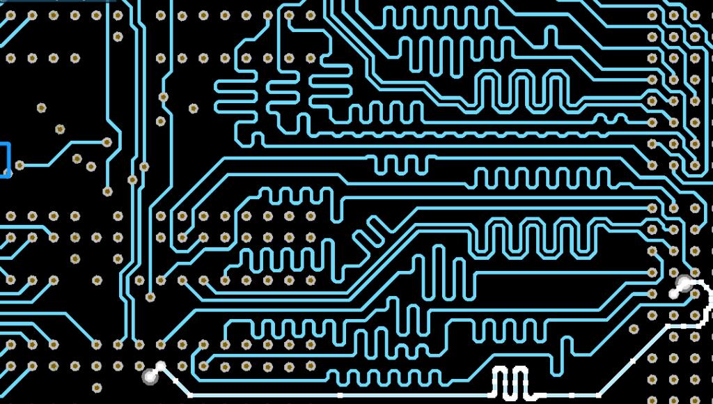
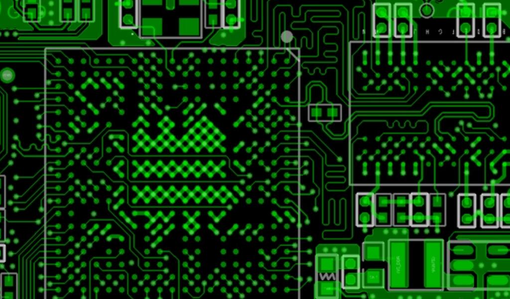
In the learning of high speed PCB design, there are many knowledge points need to understand and master, such as common signal integrity. Reflection. Crosstalk. Power noise. Filtering and so on.
1.Signal Integrity
Signal integrity (English: Signal integrity, SI) refers to the quality of the signal in the transmission path,the transmission path can be ordinary metal wire,can be optical devices,can also be other media.
At short distances.At low bit rates, a simple conductor can faithfully transmit a signal.
At long distances.If a high bit rate signal passes through several different conductors, multiple effects can degrade the signal's confidence so that the system or device cannot function properly.
As the output switching speed of integrated circuits increases and the density of PCB boards increases,signal integrity has become one of the issues that high speed PCB design must be concerned about.
Components and PCB parameters.Component layout on the PCB.High speed signal routing and other factors can cause signal integrity problems,resulting in unstable system operation or even complete failure.
Signal integrity issues to be considered are mainly ringing.Crosstalk.Ground bounce.Skew.Signal loss and noise in the power supply.

High Speed PCB Design
2.Reflection
A reflection is an echo on a transmission line.A part of the signal power (voltage and current) is transmitted on the line and reaches the load,but a part of it is reflected.
If the source and the load have the same impedance,reflections do not occur.A mismatch between the impedances of the source and the load causes reflections on the line and the load reflects part of the voltage back to the source.
If the load impedance is smaller than the source impedance,the reflected voltage is negative, and conversely,if the load impedance is larger than the source impedance,the reflected voltage is positive.
Geometry of the wiring.Incorrect wire termination.Changes in the transmission through connectors and discontinuities in the power plane can cause such reflections.
3.Crosstalk
Crosstalk is the coupling between two signal lines,the mutual inductance and mutual capacitance between the signal lines cause noise on the line.
Capacitive coupling induces coupled currents,while inductive coupling induces coupled voltages.parameters of PCB layers.Signal line spacing.The electrical characteristics of the driver and receiver and the end of the line to take over the channel have a certain effect on the crosstalk.
4.Characteristic Impedance
First of all, let's clarify a few concepts that we often see impedance.Characteristic impedance.Transient impedance, strictly speaking, they are different, but all changes do not depart from the original, they are still the basic definition of impedance:
4.1 The input impedance at the beginning of a transmission line is simply called impedance;
4.2 A signal that encounters a timely impedance at any time is called a transient impedance;
4.3 If a transmission line has a constant transient impedance, it is called the characteristic impedance of the line.
4.4 Characteristic impedance describes the transient impedance to which a signal is subjected as it travels along a transmission line, and it is a major factor affecting the integrity of the signals in a transmission line circuit.
4.5 If not specified, the characteristic impedance is generally used to refer to the transmission line impedance.
PS: For high speed PCB design, the goal is to keep the signal impedance as stable as possible during transmission, and this must be done by keeping the characteristic impedance of the transmission line stable.
5.Power Integrity
Power integrity, or PI, is the ability to verify that the voltage and current at the source and destination of a power supply meet the requirements.
Power integrity is very important in today's electronic products.There are several levels of power integrity: wafer level.Chip package level.Board level and system level.
Among them, power integrity at the board level has to meet the following three requirements:
Keep the voltage ripple at the chip pins smaller than the specification (e.g., less than +/-50 mV between voltage and 1V).
Controlling ground bounce (also known as synchro-switching noise SSN.synchro-switching output SSO)
Reducing electromagnetic interference (EMI) and maintaining electromagnetic compatibility (EMC): The power distribution network (PDN) is a board-type conductor, which is also an antenna prone to emit and receive noise.

High Speed PCB Design
6.Power Noise
Power supply noise is a kind of electromagnetic interference,the spectrum of its transmission noise is roughly 10kHz ~ 30MHz, up to 150MHz.
Power noise,especially transient noise interference,its rise speed is fast.Short duration.High voltage amplitude.Randomness is strong, on the microcomputer and digital circuitry to produce serious interference.
In high-frequency circuits,the power supply with the noise of high-frequency signals is particularly obvious.In this case,the first requirement is that the power supply is low-noise.Here, a clean ground is as important as a clean power supply.
7.Wave filtering
Wave filtering is the operation of filtering out specific wave frequencies from a signal, and is an important measure for suppressing and preventing interference.Filtering is divided into classical filtering and modern filtering.
8.Parallel bus
The parallel bus is a common physical path for communication between two or more devices, a collection of signal lines,and a common connection between multiple components for transmitting information between them.
Taking into account the different operating modes,buses can be divided into two types: one is a parallel bus and the other is a serial bus.
Parallel bus: It can transmit multiple bits of data at the same time,like a wide road that allows multiple cars to drive side by side, and it also has two-way unidirectional difference.
9.Serial bus
Serial bus:at the same time can only transmit a data,as if only allows a car to walk on a narrow road, data must be transmitted one after another.It looks like a long string of data, so it is called ‘serial’.
10.Topology
Topology refers to the form of interconnection of sites in the network,the topology of PCB design,refers to the connection between the chip.
Commonly used topologies include point-to-point.Daisy chain.Remote Cluster.Star and so on.
The above is iPCB and we share 10 high speed PCB design related important matters, I hope to help you learn.