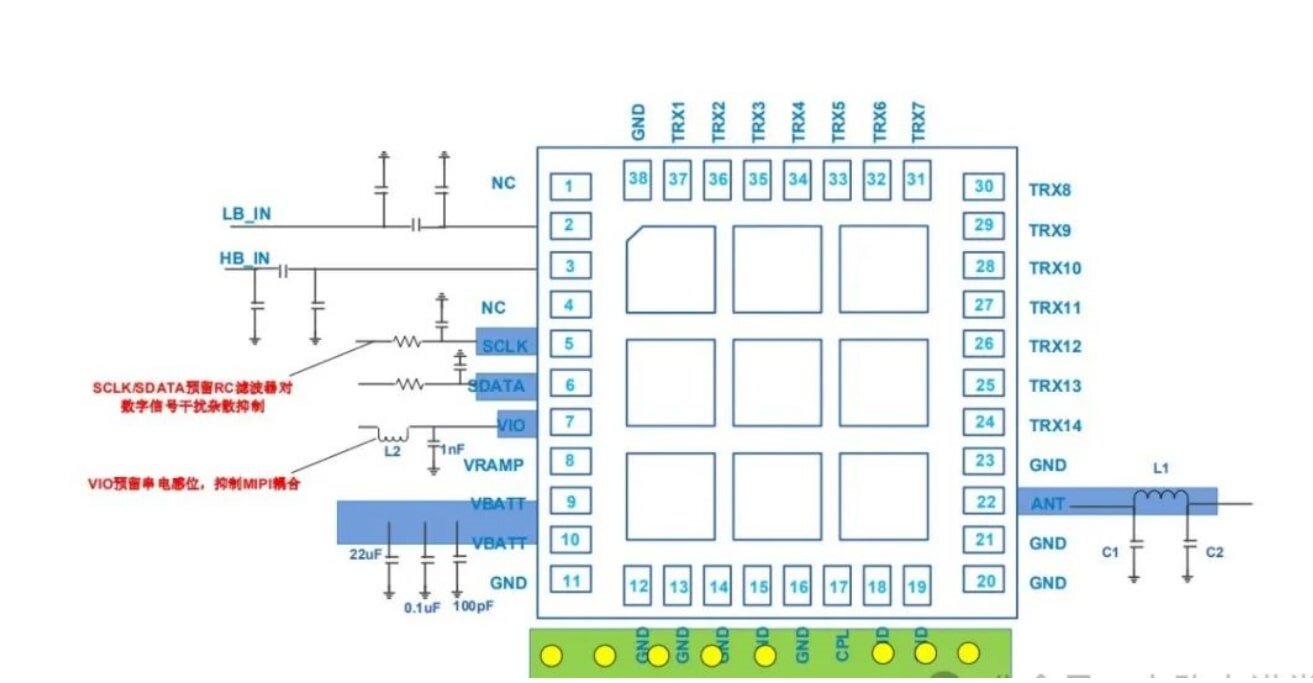
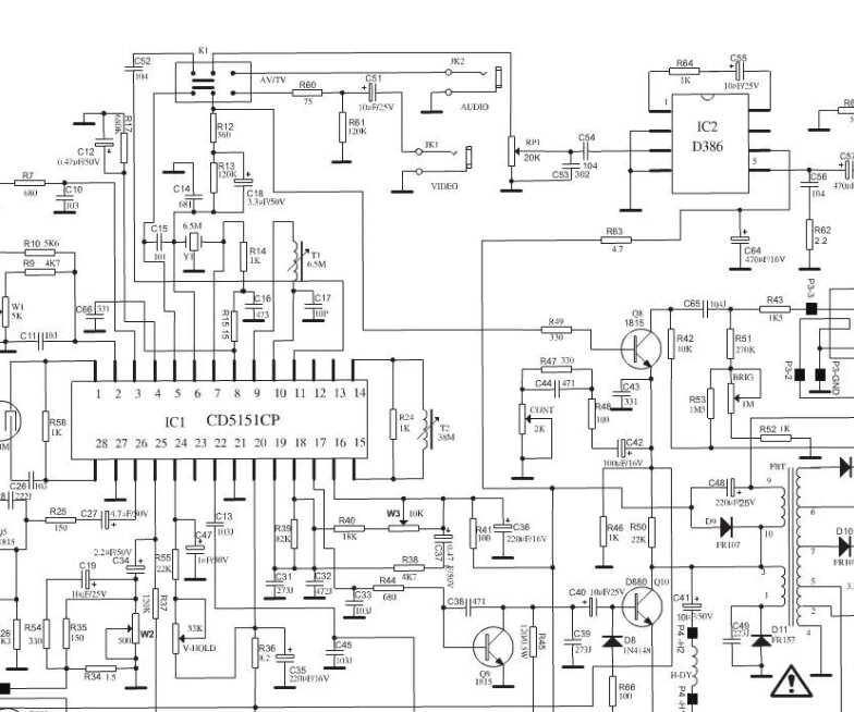
PCB circuit diagrams not only show the connection relationship of electronic components, but also indicate the specific location, layout, and electrical characteristics of components.
So how to view pcb circuit diagram?
Here are some steps and ways to view a PCB circuit diagram:
A circuit board, in fact, is an integrated body made up of a series of electronic components connected by copper foil lines. These seemingly complex lines and component arrangements actually follow specific circuit design principles. To decipher them, the first task is to familiarize yourself with common electronic component symbols.
Component Symbols: Components on circuit diagrams are usually represented by symbols, such as resistors, capacitors, transistors, integrated circuits (ICs), diodes, etc.
Electrical connections: individual components are connected together through wiring to form an electrical circuit.
Power and Ground: Circuit diagrams are labeled with power (+) and ground (-) lines to indicate reference points for voltage and current.
Signal and Ground: Signal lines are the paths through which signals are passed, and ground lines are used to return current.
Notes and labels: Some circuit diagrams will come with information such as the model number, value, and specifications of the components to help understand what each component does.
Understanding these basic symbols is the same as you have taken the first step in reading a circuit board.

pcb circuit diagram
Next, we move on to the second step - analyzing the circuit schematic.
The circuit schematic, which can be seen as the blueprint for the soul of the circuit board, shows how the components are connected and where the current goes.
How to view a pcb circuit diagram?
If you already have an actual fabricated PCB board on hand, you can view its circuit diagram in several ways:
Viewing the production files: If you have the original files from the design, they usually include the circuit schematic (.sch file) and the PCB layout (.brd file). You can open these files in your design software to view the schematic.
Check the documentation and schematic: Some products or development boards provide a user manual or development documentation that contains a schematic of the circuit, describing the function of each component and connection.
Reverse engineering: If you don't have a schematic file, you can use some tools to reverse engineer. Rebuild the circuit diagram by taking a picture of the PCB or scanning all the connections on the board and then manually parsing those connections. This process is difficult and time consuming for complex circuits, but it is feasible for simple boards.
How to Interpret PCB Circuit Diagrams
Interpreting circuit diagrams is the key to understanding and analyzing circuits. Here are a few common steps to help you read a circuit diagram:
1. Identify Components
Each component has a standard symbol in a circuit diagram. Learning and understanding these symbols is fundamental to interpreting circuit diagrams. Common symbols include:
Resistor: usually represented as a rectangular symbol with a broken line.
Capacitor: two parallel lines, electrolytic capacitors are labeled "+" sign.
Diode: a triangle pointing to a vertical line, indicating that current can only flow in one direction.
Transistors: A three-pin symbol distinguishing between NPN and PNP transistors.
Integrated circuits (ICs): a rectangular box labeled with pins, usually with more than one pin connected.

pcb circuit diagram
2. Understanding Connections
The lines in a circuit diagram represent the paths of current and connect different components. When viewing a pcb circuit diagram, you need to understand how the components are connected to each other and where the current flows in and out. Pay special attention to:
Power and Ground: identify the location of power (Vcc) and ground (GND). They are the reference points for the circuit.
Signal Path: The path a signal takes from input to output, involving components such as resistors, capacitors, and amplifiers.
Functional Modules: Circuit diagrams are often grouped by functional modules (e.g., amplifiers, filters, modems, etc.) to help you understand how the circuit works.
3. Viewing Voltage and Current Information
Some circuit diagrams will also be labeled with information about the voltage, current, or resistance of components (e.g., resistor values, forward voltage of diodes, etc.). This information helps you to understand more accurately how the circuit works.
4. Finding anomalies
If you are looking at a circuit diagram for debugging or troubleshooting purposes, you can troubleshoot by checking whether the connections on the circuit diagram make sense, looking for potential shorts or opens, or checking whether the supply voltage is correct.
This process, where you may find discrepancies between the actual board and the schematic, is where the learning opportunity lies. You will find that the circuit board designer will make adaptations to the schematic in order to consider the current level, electromagnetic compatibility and heat dissipation. Through comparative analysis and hands-on practice, you will gain a deeper understanding of the essence of circuit board design. Of course, the process of understanding the circuit board will not be easy, you may encounter a variety of challenges, such as difficult to understand the circuit symbols, intricate layout and so on.
Above are some steps and methods of "how to view pcb circuit diagram", hope it is helpful to you.