What does Dk mean?
Dk dielectric constant, also known as capacitance or relative capacitance, is an important figure characterising the electrical performance of a dielectric or insulating material. Dk is the ratio of the capacitance of a dielectric to the capacitance of a vacuum in the same capacitor with the same substance, and represents the relative ability of a dielectric to store static energy in an electric field. Dk dielectric constant represents the degree of polarisation of the dielectric, that is, the ability to bind charges, the higher the dielectric constant, the stronger the ability to bind charges. For dielectric materials, the larger the Dk, the larger the capacitance.
Df loss factor, also known as the damping factor or internal dissipation (internal dissipation) or loss tangent (loss tangent), Df is the loss angle of the PCB circuit board data, the signal in the data transfer is not entirely along the signal path forward, there will be a part of the material through the inflow of the conductor in the vicinity. Df is used to express the ratio between the energy flowing into nearby conductors (lost) and the energy travelling along the signal path.
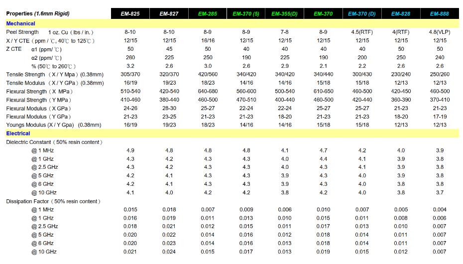
Dk and Df are often the key factors used to evaluate the loss in a transmission line.Dk and Df generally change with frequency and temperature and humidity, Dk decreases as frequency increases, Df increases as frequency increases, different circuit board data Dk and Df with the external environment (frequency and temperature and humidity, etc.) of the rate of change is different, generally the smaller the rate of change of the circuit board data is more stable.
Generally to high-speed design,we are pursuing high-speed boards, that is, the Df is smaller, for the two kinds of boards, if the Df is almost the same, choose Dk small or large?
The choice of Dk is mainly to see whether the impedance can be satisfied, in addition to choosing Dk small in the same stack under the same impedance requirements of the line width will be a little wider, so that the high-speed signal is better, the same impedance is the same case,the line width of the conductor loss is small, from the loss of the formula, the Dk small loss will be relatively small, so if it is a high-speed signals and the alignment of the line is very long, of course, the Dk small will be good point.
Our commonly used circuit board PCB dielectric is FR-4 data,relative to the air dielectric constant is 4.2-4.7.This dielectric constant will change with the temperature, in the 0-70 degrees Celsius temperature range, the maximum range of change can be up to 20%. Changes in the dielectric constant will cause a 10% change in line delay,the higher the temperature, the greater the delay. The higher the temperature, the greater the delay. The dielectric constant also changes with the signal frequency, the higher the frequency the smaller the dielectric constant.

High Frequency Circuit Board
Factors affecting the dielectric constant of Dk
1.Polarity
General non-polar data,such as PE,PP,PS,etc.Dk number is small,about 2 ~ 3 ε 0.The low-level data dielectric constant is 3 ~ 5;polar data Dk is 4 ~ 10,strong polarity is even larger;
The dielectric constant of low-level data is 3~5;the Dk of polar data is 4~10,and that of strong polarity is even larger.The higher the symmetry of the molecular chain,the smaller the dielectric constant.
For example, the dielectric constant of F4 in plastics is the smallest,only 2.1;PA6 is higher, 4.7.
2.Electric field frequency
Low-frequency electric field frequency change has little effect on Dk,high-frequency electric field has a greater impact,because the polarisation reaction needs a certain amount of time,so in high-frequency frequency increase, polarisation rate of polarised data is not enough to respond to the decrease in dielectric constant,the frequency decreases is the dielectric constant becomes larger.For non-polarised data,because of the symmetry of molecular chain, so the dielectric constant is not sensitive to frequency change.
3.Ambient Temperature
When the temperature rises, the dielectric constant of non-polar data does not change much,while the dielectric constant of polar data increases,but when the temperature rises to a certain value, it will decrease with the rise of temperature; the polarities are sensitive to the change of temperature.This phenomenon also occurs in non-polar data,but the change is very small.These two kinds of data in the Tg or Tm point will occur in the dielectric constant increase phenomenon.
4.Relative humidity
When the humidity increases, the Dk dielectric constant becomes larger,which has a greater effect on polar data.This is because water is a polar medium.
The water film on the surface of the plastic will increase the surface conductivity and promote the polarisation of the data. When the frequency is low, the effect of water absorption is greater. As the frequency increases, the effect becomes smaller.

Relationship between Dk and Df and frequency
Relationship between Dk and Df and frequency
The higher the frequency,the more Dk decreases monotonically.
The higher the frequency,the higher the Df is likely to rise and then fluctuate slightly.
According to the level of Df loss factor,PCB substrates can be classified into five levels:
Standard Loss (Df:0.015-0.020)
Mid Loss (Df:0.010-0.015)
Low Loss (Df:0.0065-0.01)
Very Low Loss (Df:0.003-0.0065)
Ultra Low Loss (Df:<0.003)
The smaller the Df,the lower the dielectric loss.
Conductor loss and dielectric loss,the total loss of PCB transmission line is called insertion loss (α t).It is the sum of Conductor loss (α c), Dielectric loss (α d), Radiation loss (α r) and Leakage loss (α l). The effect of leakage loss is negligible because of the high volume resistance of the PCB.
Radiation loss is the amount of energy lost in the circuit due to radio frequency radiation.The loss depends on frequency, dielectric constant (Dk) and thickness.For a given transmission line, the loss is higher at higher frequencies. For the same circuit, when a thinner substrate with a higher Dk value is used,the radiation loss will be smaller and generally negligible.
With the progress of electronic design technology and manufacturing technology,electronic products are gradually to high-density, high-function,thin and short,high transmission rate direction. In addition, with the rapid development of chip miniaturisation and the increase in data transmission,the operating frequency of the system is getting higher and higher.To become an excellent electronic product, not only need excellent circuit design, but also need good manufacturability,because good manufacturability can reduce the number of problems in production,shorten the product development progress,reduce design costs, and thus improve product competitiveness. Therefore, it is very important for product design engineers to choose PCB materials when designing electronic products.
When the circuit's operating frequency in the radio frequency band, design engineers can choose the scope of the circuit board will be greatly reduced. For example, Rogers ro4835 high frequency boards are specially formulated to improve oxidation resistance. This provides exceptional electrical stability for long-term use at certain temperatures,while maintaining the processing advantages of FR4 thermoset resins. The material also has a dielectric constant (DK) of 3.48, a dielectric loss (DF) of 0.0037 at 10 GHz and a low z-axis coefficient of thermal expansion (CTE), which ensures reliability under a wide range of machining and operating conditions in metal through-holes. The x-axis and y-axis coefficients of expansion of the material are similar to those of copper, providing excellent dimensional stability.
With the communication technology from 2G, 2.5G, 3G to 4G and now 5G, data transmission throughput is getting bigger and bigger,the required bandwidth is getting wider and wider, and the frequency is getting higher and higher; the miniaturisation of equipment is also one of the future development trends, once the equipment becomes smaller,PCBs are required to have a higher coefficient of thermal conductivity and a higher Dk dielectric constant. High-frequency PCB materials are mainly used in high-power amplifiers, base station antennas, global positioning systems (GPS),meteorological radars and satellites,automotive radars and sensors.
The main parameters of PCB materials are DK and DF, in high frequency circuit boards, the stability of the DK value is the guarantee of the reliability of the board, and the DF value should be as small as possible to reduce the signal loss. Moreover, in some high-speed and large-scale data transmission systems, some high-frequency circuit boards with low DK and DF are also used.