1. Introduction
A PCB reflow oven is a heating system used for soldering surface-mounted components (SMCs) onto printed circuit boards (PCBs).
Common types of PCB reflow ovens include:
Infrared ovens
Hot-air ovens
Infrared hot-air ovens
Vapor phase ovens
Currently, full hot-air ovens are the most widely adopted in the electronics manufacturing industry.
2. Heat Transfer Mechanisms in Reflow Soldering
Three basic mechanisms are involved in heat transfer during soldering:
2.1 Thermal Conduction
Heat transfer from a higher-temperature region to an adjacent lower-temperature region, or from a hot object to a cooler object in contact, without material movement.
2.2 Thermal Convection
Heat transfer caused by the movement of fluids at different temperatures. The intensity depends primarily on the convection flow pattern.
2.3 Thermal Radiation
Heat transfer via electromagnetic radiation with wavelengths between 0.1 μm and 100 μm, enabling energy transmission even through a vacuum.
Practical Heat Transfer in Ovens:
Hot-air oven – dominated by convection and conduction.
Infrared oven – dominated by radiation.
Full hot-air PCB reflow oven (BGA soldering) – convection mainly affects outer solder balls, conduction dominates in the center.

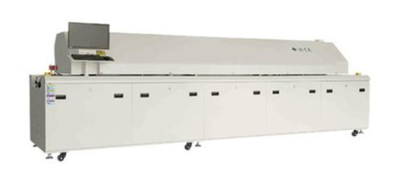
PCB reflow oven
3. Classification of PCB Reflow Ovens
3.1 By Heating Scope
Full PCB heating – Batch type / Inline type
Localized PCB heating – Specific component or area
3.2 Full PCB Heating Methods
1. Hot-plate reflow soldering – Mainly for ceramic substrates.
2. Infrared reflow soldering – Non-uniform heating, large temperature gradients, poor for quality control.
3. Hot-air reflow soldering – Uniform heating, good soldering quality. Limitations: difficult vertical temperature control, high energy use. Currently the industry’s preferred choice for PCB reflow ovens.
4. Hot-air + infrared reflow soldering – Improves heating efficiency and energy savings.
5. Vapor phase reflow soldering – Highly accurate temperature control, oxygen-free environment, uniform heating, unaffected by component layout; high soldering quality. Limitations: high cost, potential toxic gas emissions.
3.3 Localized PCB Heating Methods
1. Laser reflow soldering / Beam reflow soldering – Heat applied only to solder joints; prevents damage to components and substrates; high quality and repeatability; very fast for single points; high equipment cost; used for special components.
2. Hot-gas reflow soldering – Requires nozzles matched to solder joint size; slower speed; used for rework or prototyping.
3. Focused infrared reflow soldering – Suitable for rework stations.
4. Basic Structure of a Hot-Air PCB Reflow Oven
A hot-air PCB reflow oven generally consists of:
1. Furnace body
2. Upper and lower heating modules
3. PCB conveyor system
4. Air circulation system
5. Cooling unit
6. Exhaust system
7. Temperature control system
8. Exhaust gas recovery system
9. Computer control system
5. Key Technical Specifications of PCB Reflow Oven
Temperature control accuracy: ±0.1~0.2 °C
Cross-belt temperature variation: ≤±5 °C; for lead-free soldering ≤±2 °C
Temperature profile measurement: If not built-in, an external temperature profiler should be used
Maximum heating temperature: Generally 300–350 °C; for lead-free solder or metal substrates, select ≥350 °C
Number and length of heating zones: More zones and longer heating length allow easier temperature profile adjustment and control
Conveyor width: Determined by the maximum PCB size