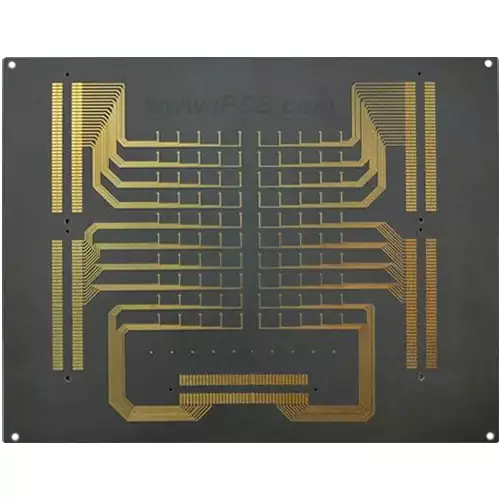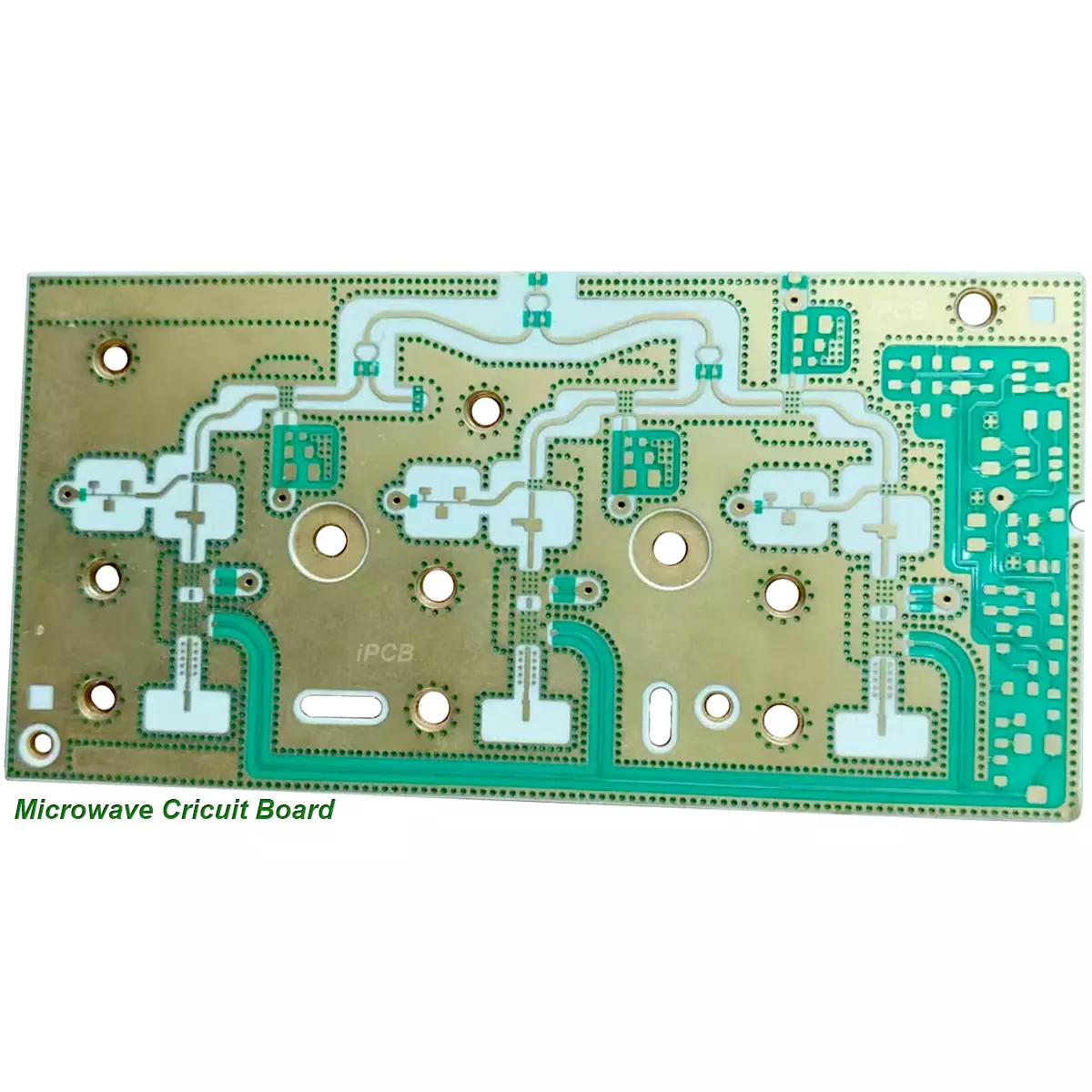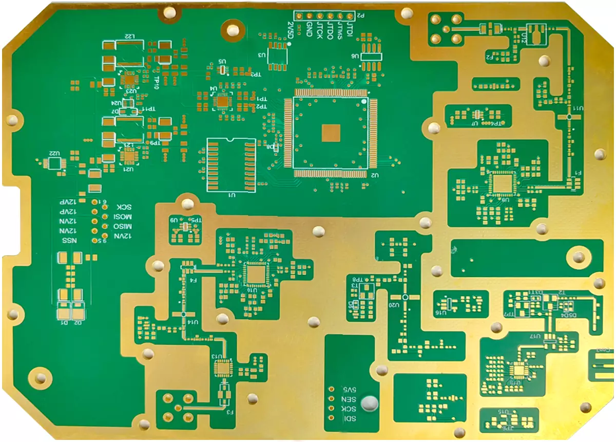

Product: Microwave Cricuit Board
Material: PTFE, Teflon, FR-4
Layer: Single sided, double-layer, multi-layer
DK: 2.2-16
Medium thickness: customizable
Base copper thickness: 0.5oz, 1oz
Outer copper thickness: 1oz, 2oz
Finished PCB thickness: 0.2-12mm
Solder mask colors: green, red, blue
Surface treatment: ENIG
Application: antennas, communication
Microwave circuit board is a printed circuit board specifically designed and manufactured for Radio Frequency circuits. Microwave circuit boards have excellent signal transmission performance and are widely used in high-frequency applications such as 5G base stations and satellite communications.
There are various types of materials used in microwave circuit boards, among which polyimide (PI), PTFE (polytetrafluoroethylene) and other microwave circuit boards are specifically designed for processing high-frequency signals and have low dielectric constants and loss factors. These microwave circuit boards have characteristics such as low loss, low dielectric constant, and low dielectric loss factor, which can ensure stable transmission of RF signals.
More and more device designs are entering the microwave frequency band (>1GHz), and even expanding to the millimeter wave field (such as 77GHz), especially in applications such as vehicle mounted 77GHz millimeter wave radar. This trend not only drives the continuous increase in frequency, but also puts forward higher requirements for the substrate of circuit boards. Microwave circuit board substrates need to have excellent electrical properties, stable chemical properties, and minimal losses on the substrate as the frequency of the power signal increases. Therefore, the importance of microwave circuit boards is becoming increasingly prominent.
When selecting PCB substrate materials for microwave circuits, it is important to focus on several key indicators of the materials.
The variation characteristics of the dielectric constant (DK) of materials at different frequencies must be considered. For applications that focus on high-speed signal transmission or characteristic impedance control, special attention needs to be paid to the dissipation factor (DF) of materials and their performance under different frequency, temperature, and humidity conditions.
General substrate materials usually exhibit a large variation pattern of DK and DF values when the frequency changes. Especially in the frequency range of 1 MHz to 1 GHz, this change is particularly evident. For example, the DK value of a typical epoxy resin fiberglass cloth based substrate material (such as FR-4) is 4.7 at a frequency of 1 MHz, while at a frequency of 1 GHz, the DK value varies to 4.19. After exceeding 1 GHz, the trend of DK value gradually becomes flat, but as the frequency increases, its value will still slightly decrease (although the magnitude of the change is not significant). At a frequency of 10 GHz, the DK value of FR-4 is approximately 4.15.
The microwave circuit board material with high-speed and high-frequency characteristics has a relatively small change in DK value when the frequency changes. Within the frequency range of 1 MHz to 1 GHz, the DK value mostly remains within the range of 0.02. Meanwhile, under different frequency conditions, its DK value also shows a slight downward trend.
The dielectric loss factor (DF) of general substrate materials usually varies more than DK in frequency, especially in the high-frequency range, and often shows an increasing trend. Therefore, when evaluating the high-frequency characteristics of a microwave circuit board material, the variation of DF value needs to be carefully examined.
There are usually two types of DF value variation characteristics of microwave circuit boards with high-speed and high-frequency characteristics at high frequencies: one is that their DF value changes very little with frequency; Another type is similar in magnitude to general substrate materials, but the DF value of the microwave circuit board itself is lower.

microwave circuit board
The main factors to consider when choosing a suitable microwave circuit board
1. Manufacturability: including multiple compression performance, temperature stability, CAF/heat resistance, mechanical toughness (reliability), fire rating, etc. These factors are crucial for the manufacturing process of microwave circuit boards and the quality of the final product.
2. Performance matching with the product: Mainly considering electrical performance and stability, such as low loss, stable Dk/Df parameters, low dispersion, and small coefficient of variation with frequency and environment. The small tolerance of material thickness and adhesive content is helpful for impedance control. For long cables, consider using low roughness copper foil.
3. Material availability: The procurement cycle for many microwave circuit boards is relatively long, possibly up to 2-3 months. Except for conventional microwave circuit boards (such as Rogers RO4350B, Rogers RO4003C) that are in stock, other microwave circuit boards often require customers to communicate with PCB manufacturers in advance and prepare materials.
4. Cost factor: Evaluate the cost based on the price sensitivity of the microwave circuit board of the product and its application areas (such as consumer, communication, medical, industrial, military, etc.).
5. Applicability of laws and regulations: Ensure that microwave circuit boards comply with environmental regulations in different countries, such as RoHS PCB and halogen-free PCB.
In practical applications of Radio Frequency circuits, it is necessary to conduct specific analysis based on specific cases to ensure the smooth progress of the microwave circuit board manufacturing process and the performance standards of the final product.
iPCB is a manufacturer mainly engaged in the production of high-frequency, high-speed, microwave RF printed circuit boards. The main products include microwave circuit boards Rogers PCB、RF PCB、Taconic PCB、Arlon PCB, Antenna PCB, F4BM PCB, power amplifier PCB, microwave PCB, etc.
Product: Microwave Cricuit Board
Material: PTFE, Teflon, FR-4
Layer: Single sided, double-layer, multi-layer
DK: 2.2-16
Medium thickness: customizable
Base copper thickness: 0.5oz, 1oz
Outer copper thickness: 1oz, 2oz
Finished PCB thickness: 0.2-12mm
Solder mask colors: green, red, blue
Surface treatment: ENIG
Application: antennas, communication
iPCB Circuit provides support for PCB design, PCB technology, and PCBA assembly. You can request technical consultation or quotation for PCB and PCBA here, please contact email: sales@ipcb.com
We will respond very quickly.