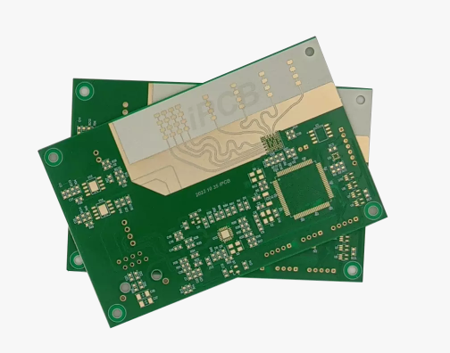
Millimeter-wave radar is a high-precision sensor used to measure the relative distance, speed, and orientation of objects. It utilizes the principles of propagation and reflection of
electromagnetic waves to determine the position data of a target by transmitting millimeter-wave signals and receiving echo signals. Its working principle is to send out
the radio wave (millimeter wave), and then receive the echo, according to the time difference between sending and receiving to measure the target's position data and relative distance,
the frequency band is generally between 10GHz and 200GHz. Currently, millimeter-wave radar technology is widely used in unmanned vehicles, the reason is that such
a frequency makes millimeter waves in the field of vehicle performance, can penetrate rain, snow, and other harsh weather conditions without being affected, can effectively
enhance the vehicle in the complex environment perception ability.

When designing a millimeter wave radar PCB, special attention must be paid to its structure, materials, and manufacturing process.
- Material Requirements
For 77GHz millimeter wave radar, it is necessary to choose RF materials with stable dielectric constant and low loss, such as Rogers's high-frequency sheet, which can ensure that
the antenna can accurately obtain the phase and improve the antenna gain and scanning angle.
- Design Structure
Proper wiring and structural layout are needed to minimize signal interference and energy loss. Microstrip and GCPW are used to optimize HF operation and improve
antenna gain and scan angle.
- Surface Finish
A good surface finish reduces signal reflection and loss and improves the accuracy and stability of radar measurements. The accuracy and stability of a millimeter wave radar rely on
the performance of its PCB, and PCB surface treatment can significantly affect the signal transmission effect. Millimeter-wave radar PCB commonly used surface treatment that has
immersed silver, tin plating, immersed gold, and so on. Immersed gold surface treatment has better conductivity and oxidation resistance; immersed silver cost is lower than immersed gold,
but it is very easy to oxidize in contact with air; tin plating cost is lower compared to the first two, but there may be signal attenuation in high-frequency applications. Selection of
high-temperature and moisture-resistant surface treatment can ensure the reliability and longevity of the PCB in a variety of environments.
In addition to the considerations above, the PCB manufacturer's production process is very important. To ensure the performance of millimeter-wave radar PCBs, a variety of testing and
verification methods must be performed, including RF parameter verification, and power and frequency testing. An effective test program can confirm that the dielectric properties and
loss performance of the selected materials meet the design criteria, which in turn affects the performance of the transmitting and receiving antennas.