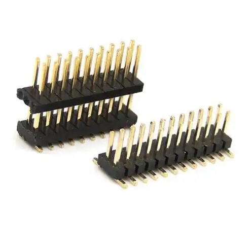
PCB headers, also known as connectors or sockets, are components used to make electrical connections in electronic devices. They can be single-row, double-row, or multi-row, and come in a variety of PCB pin types to suit different applications.
The following are some common PCB header pin types:
1. Through-Hole: This is the most traditional type of PCB pins, they are inserted from one side of the PCB, and then extended from the other side, usually used for larger devices or applications that require mechanical stability.
2. Surface-Mount: this PCB pin type directly mounted on the surface of the PCB, do not need to penetrate the PCB, they are suitable for miniaturization and high-density electronic design.
3. Box Header: This PCB pin has a rectangular shape, usually used for the need for frequent insertion and removal of the occasion, such as programming interfaces.
4. Round Pin: round pin is the most common PCB pin shape, they can be direct or surface mount type.
5. Flat Pin: flat pins have a large contact area, suitable for high current or signal integrity requirements of higher applications.
6. Latching Pin: This pin is designed with a locking mechanism to ensure that the connector will not accidentally fall off when connected.
7. Spring Pin: elastic pin with elasticity, can be connected to provide better contact force, suitable for vibration or shock environment.
8. Dual Row Pin: double row of pins on both sides of the PCB have pins, for the need for more pins but limited space applications.
9. Variable Pin: This pin can be configured as needed, for example, by changing the location or number of pins to adapt to different interface requirements.
10. Shielded Pin: Shielded pins are designed with a shielding layer, which can reduce electromagnetic interference, suitable for applications requiring very high signal integrity.
11. High Voltage Pin: This pin is designed to withstand higher voltages, suitable for power electronics or high-voltage test equipment.
12. RF Pin: RF pins designed to transmit high-frequency signals, they usually have a specific impedance matching characteristics to minimize signal loss.
13. Differential Signal Pin: Differential signal pins are used to transmit differential signals, which can improve the signal's immunity to interference.
14. Power Pin: power pins designed to transmit power, they usually have a larger size and current carrying capacity.
15. Signal Pin: Signal pins are used to transmit data or control signals, their design is usually considered signal integrity and minimize crosstalk.

PCB header
The following are some common PCB pin specifications:
1. Pin spacing: pin spacing is the distance between the centers of two adjacent pins. Common PCB pin spacing is 0.1 inches (2.54mm), 0.05 inches (1.27mm), 0.025 inches (0.635mm) and so on.
2. Pin diameter: the diameter of the pin determines the size of the current it can withstand. Common PCB pin diameter of 0.008 inches (0.2mm), 0.016 inches (0.4mm), 0.032 inches (0.8mm) and so on.
3. The length of the pin: the length of the PCB pin can be customized according to the need to adapt to different installation depths and board thickness.
4. Pin Shape: The shape of the PCB pins can be straight, curved or with special shapes to adapt to different connection methods and mechanical requirements.
5. Pin material: pins are usually made of copper or tinned copper to provide good electrical conductivity. Some pins may be gold-plated or silver-plated to improve corrosion resistance and signal transmission quality.
6. The number of pins: the number of pins in the header can vary from a few to dozens, depending on the complexity of the application and the number of electrical connections required.
7. The PCB pin arrangement: the pins can be arranged in accordance with a straight line, round, matrix or other specific patterns to adapt to different circuit board layouts and space constraints.
8. Pin locking mechanism: In order to prevent accidental dislodgement of the connection, some headers are designed with a locking mechanism, such as clips, screws or spring clamps.
9. The pin contact type: the pin contact type can be crimped, soldered or plugged to adapt to different installation methods and electrical performance requirements.
10. Pin insulating material: In order to ensure electrical isolation and mechanical strength, the pins may be used around the plastic or other insulating materials.
11. Pin plating: In addition to gold and silver plating, the pin may also use other metal plating, such as nickel, tin or zinc, in order to improve corrosion resistance and soldering performance.
12. Environmental adaptability: according to the application of different environments, the PCB pin may need to have high temperature resistance, moisture resistance or other special environmental adaptability.
When selecting the header, you need to consider the above specifications to ensure its compatibility with the circuit board and other electronic components. In addition, factors such as mechanical strength, electrical performance, cost and availability of the headers need to be considered. When designing and selecting a header, it is often necessary to refer to relevant industry standards and manufacturer's specifications.
Each pin type has its specific application scenarios and advantages, and engineers need to select the appropriate PCB pin type according to specific application requirements when designing PCBs. In addition, the PCB pin material, plating, insulator, etc. are also factors that need to be considered when designing to ensure the performance and reliability of the connector.