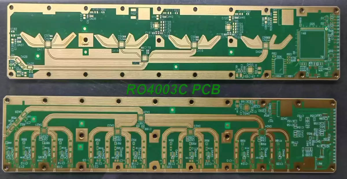
RO4003C is a high-frequency PCB substrate material produced by Rogers. The dielectric constant Dk of RO4003C is 3.38±0.05, and the dielectric loss Df at 10 GHz is 0.0027, showing low dielectric loss characteristics. The material is made of a proprietary glass cloth reinforced, ceramic-filled hydrocarbon composite material, combining the electrical performance of PTFE/glass cloth and the processability of epoxy resin/glass cloth.
RO4003C offers two different configurations of glass cloth options (1080 and 1674), but all configurations maintain the same electrical performance specifications. Its Z-axis coefficient of thermal expansion (CTE) is 46ppm/℃, which is similar to copper material, giving the material excellent dimensional stability. When experiencing thermal shock, RO4003C's low Z-axis CTE ensures the quality of plated through holes. In addition, the RO4000 series materials have a glass transition temperature (Tg) of over 280°C (536°F), remain dimensionally stable throughout the circuit processing process, and have the same mechanical properties as standard epoxy/glass processing, but at a much lower cost than traditional microwave laminates.
RO4003C high-frequency PCB substrate materials are fully compatible with traditional PCB circuit board manufacturing technologies, do not require special through-hole copper plating pre-treatment (such as plasma treatment required for PTFEPCB substrate materials) or other pre-treatment processes, and support grinding operations in the solder mask process. However, RO4003C high-frequency PCB substrate materials are not brominated and therefore cannot meet the UL 94V-0 flame retardant rating standard. For applications that require this flame retardant rating, consider using RO4835 or RO4350B high-frequency PCB substrate materials.

RO4003C PCB
The main features of RO4003C include: low dielectric constant tolerance and low loss characteristics, similar processing technology to FR-4, but lower cost, designed for performance-sensitive high-capacity applications, stable electrical characteristics at different frequencies, and low Z-axis thermal expansion coefficient.
Typical application areas include: microstrip lines, cellular base station antennas, automotive radar and sensor systems, point-to-point microwave communication systems, power amplifier components, RFID antennas.
When electronic engineers select PCB substrate materials during simulation design of PCBs, they should consider whether the operating frequency of the PCB substrate material meets the requirements of the product. The main parameters that affect the operating frequency of PCB substrate materials are whether the dielectric constant and its changes meet the design requirements within a certain bandwidth. In addition, the dielectric constant also affects the line width of the transmission line or matching line. The smaller the dielectric constant Dk value, the wider the transmission line. Using materials with different dielectric constants requires re-simulation and design of the line width.
Under the same conditions, the smaller the loss factor of the PCB substrate material, the smaller the signal loss during transmission. Both RO4003C and RO4350B have extremely low loss factors. During the transmission process, the transmission line loss of RO4350 is greater than that of RO4003C. When the system gain design margin is tight, the selection of RO4003 with a smaller loss factor can reduce the transmission loss of the dielectric board.
Temperature changes in the product use environment will also cause the size of the PCB to expand and shrink. For PCB, the copper layer (including through holes) is pressed with the dielectric material at room temperature. As the temperature changes, the copper and the dielectric have different thermal expansion coefficients with the change of temperature.
Due to inconsistent expansion coefficients, temperature stress will inevitably occur. When the temperature stress exceeds the bearing capacity of the copper layer, the dielectric, or the bonding between the copper layer and the dielectric, the PCB board will be damaged. Temperature stress in the Z-axis direction may cause the metallized through hole to break, and repeated stress in the X/Y axis may cause the copper layer to tear or the bonding between the copper layer and the dielectric to loosen. When processing the PCB substrate material, due to etching shrinkage (baking after etching), the different thermal expansion coefficients will cause the size of the PCB substrate material to change after processing.
Of course, when choosing PCB substrate materials, in addition to paying attention to the above-mentioned main parameters, other performance indicators of PCB substrate materials should also be considered according to the actual application environment, such as copper foil peeling strength, thermal conductivity, flame retardant grade, high temperature lead-free process, cost, etc., and fully understand the actual application environment and the meaning of each parameter of PCB substrate materials, so as to choose the most suitable PCB substrate material.
iPCB is mainly engaged in the production of high-frequency, high-speed, microwave and radio frequency PCB circuit boards. The main products are: microwave radio frequency high-frequency board, Rogers high-frequency board, Rogers multi-layer high-frequency mixed board, Rogers radio frequency board, Rogers RO4003C, Taconic microwave board, Taconic multi-layer circuit board, Arlon microstrip antenna board, ARLON high-frequency board, F4BM antenna board, F4BM multi-layer mixed board, RF power amplifier PCB board, HDI precision multi-layer board, providing PCB circuit board customization services for global electronic manufacturing and R&D.