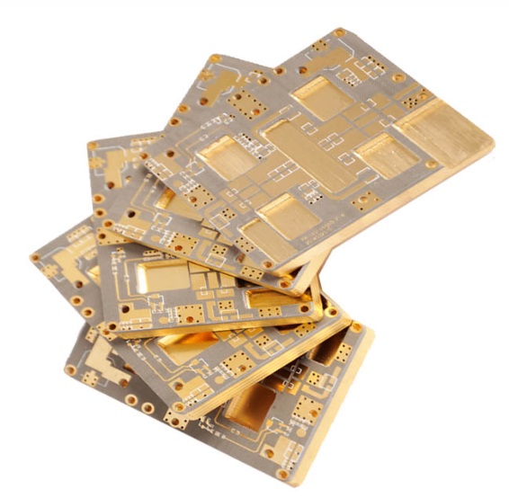
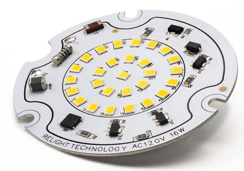
As electronic devices evolve to become smaller, faster, and more powerful, thermal management and structural reliability have become two of the most critical factors for high-performance designs. This is where metallic substrates — also known as metal-core or metal-based substrates — offer a distinct advantage over traditional PCB materials like standard FR4.
What is a Metallic Substrate?
In the context of printed circuit boards (PCBs), a metallic substrate refers to a structure that uses a metal (typically aluminum, copper, or steel) as the base material instead of a pure dielectric or resin system. The metal core acts as both a mechanical backbone and a heat sink, significantly improving thermal conductivity and structural integrity.
The most common form is the Metal Core Printed Circuit Board (MCPCB), which usually consists of three main layers:
Copper Foil Circuit Layer: The top layer where circuits are etched.
Dielectric Insulation Layer: A thermally conductive but electrically insulating layer that isolates the circuit from the metal base.
Metal Base Layer: Usually aluminum or copper, which acts as the heat dissipation path.
Why Use Metallic Substrates?
1. Superior Thermal Conductivity
One of the biggest pain points in power electronics, high-power LEDs, and automotive applications is heat buildup. Excess heat degrades performance, reduces lifespan, and can cause failure. Metallic substrates, especially aluminum-based ones, typically offer thermal conductivities in the range of 1.0 to 4.0 W/mK — significantly higher than standard FR4, which is around 0.3 W/mK.
For example, in high-brightness LED modules, a well-designed aluminum MCPCB can reduce junction temperature by up to 20–30°C compared to FR4. This translates directly into longer LED lifespan and higher lumen maintenance.
2. Enhanced Mechanical Strength
Using a metal base gives the PCB improved dimensional stability and better vibration resistance. This is crucial in applications like automotive lighting or outdoor industrial equipment, where boards are exposed to constant thermal cycling and mechanical shocks.
3. Improved Heat Dissipation with Direct Mounting
In many MCPCB designs, components can be mounted in such a way that they have a direct thermal path to the metal base. This minimizes thermal resistance and often eliminates the need for bulky heatsinks, reducing both assembly cost and system weight.
Common Metallic Substrate Materials and When to Use Them
Aluminum:
Most widely used due to its excellent balance of cost, thermal conductivity (around 1.0–2.0 W/mK for the dielectric), and lightweight properties. Common in LED lighting, automotive headlamps, and power supplies.
Copper:
Offers even higher thermal conductivity and better mechanical performance but comes at a higher cost and weight. Used in extremely high-power applications, like power modules or RF amplifiers where heat flux is exceptionally high.
Steel:
Less common, mainly used for structural rigidity when weight is less of an issue. Its thermal performance is lower than aluminum or copper.

Real-World Applications
1. LED Lighting Modules
This is arguably the largest commercial application for metallic substrates. High-power LEDs require efficient heat transfer to maintain light output and lifespan. MCPCBs with aluminum bases are standard in downlights, street lamps, and automotive LED headlamps.

2. Power Electronics
DC-DC converters, inverters, and power supply units benefit from metallic substrates due to better thermal dissipation at high currents.
3. Automotive and Aerospace Electronics
Vibration resistance, structural strength, and heat management make metallic substrates attractive for control units mounted close to engines or other high-temperature zones.
Design Considerations: It’s Not Just Plug-and-Play
While the benefits are clear, engineers must carefully design the stack-up:
Dielectric Layer Thickness: Thinner layers improve thermal transfer but may increase the risk of breakdown voltage issues.
Thermal Via Integration: In some designs, adding thermal vias can further improve heat conduction to the metal base.
Surface Finishing: ENIG (Electroless Nickel Immersion Gold) and HASL (Hot Air Solder Leveling) finishes must be chosen based on component type and mounting method.
Another key factor is ensuring good insulation between the circuit layer and the metal base to prevent short circuits, especially under high-voltage or high-frequency conditions.
Trends and Innovations
Material manufacturers are continuously improving the thermal conductivity of the dielectric layer. Some advanced MCPCBs now reach over 8–10 W/mK, expanding their use into next-generation applications like electric vehicle battery management and 5G RF modules.
In addition, hybrid solutions combining metal cores with ceramic or high-frequency laminates are becoming more common to meet demanding signal integrity and thermal requirements simultaneously.
Final Thoughts
Metallic substrates have gone far beyond niche use and are now a critical enabler for modern high-power, high-reliability electronic systems. By leveraging their superior thermal performance and mechanical strength, designers can unlock better performance, higher power density, and longer lifespans for their products.
For PCB fabricators and OEMs alike, understanding how to optimize metallic substrate design — from material selection to stack-up and processing — is key to staying competitive as devices continue to shrink and power demands grow.
Need help selecting the right metallic substrate for your next design?
Our engineering team has extensive experience with aluminum, copper, and hybrid metal-based PCBs for a wide range of industries. Feel free to reach out anytime — we’re happy to share insights and support your next project!