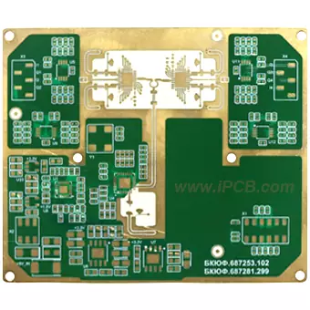
Product: RO3010 PCB
Material: Rogers RO3010
Layer: 2L
RO3010 Dk: 3.0
RO3010 Df: 25mil (0.64mm)
RO3010 base copper thickness: 0.5oz
Outer copper thickness: 1oz
Finished PCB thickness: 0.75mm
Solder mask colors: Green
Surface treatment: ENIG
Application: radar, instrument
Rogers RO3000 series RF circuit board material is a ceramic filler composite material based on PTFE, which is quite competitive in price. Some models are reinforced with woven glass cloth. This series of products has a wide range of dielectric constants, the lowest dielectric loss tangent among commercial grade materials (0.0016), and a low Z-axis thermal expansion coefficient.
RO3010 has become the preferred material for high dielectric RF circuits with a dielectric constant of 10.2 and excellent mechanical properties. RO3010 not only provides excellent electrical performance, but also has stable thermal performance and low dielectric loss. It is widely used in RF amplifiers, antenna arrays, and millimeter wave radar systems, and is an ideal choice for achieving circuit miniaturization and high performance.
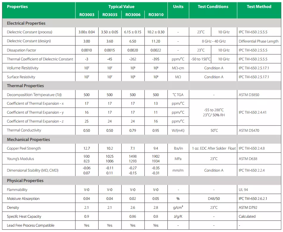
RO3010 and RO3006 are PTFE composite materials with added ceramic fillers, suitable for commercial microwave and radio frequency applications. These laminates exhibit excellent dielectric constant stability with temperature changes and eliminate the dielectric constant step phenomenon that occurs in PTFE glass cloth materials near room temperature. In addition, the RO3006 and RO3010 laminates exhibit very low dielectric losses at 10GHz, with values of 0.0020 and 0.0022, respectively.
Compared to RO3003, RO3010 and RO3006 have higher dielectric constants.
Applications of RO3010: power amplifier, RF coupler, aerospace, national defense

RO3003, RO3035, RO3006, RO3010
Both RO3010 and RO3006 belong to the RO3000 series, so what is the difference between RO3010 and RO3006?
1. Dielectric constant (Dk)
The dielectric constant of RO3006 is 6.15, while the dielectric constant of RO3010 is even higher, reaching 10.2. The dielectric constant is an indicator of a material's ability to store electrical energy and has a direct impact on signal transmission speed and delay in circuit design.
2. Loss factor (Df)
The loss factor of RO3006 is 0.0020@10GHz The loss factor of RO3010 is 0.0022@10GHz . The lower the loss factor, the smaller the signal attenuation of the material during high-frequency signal transmission, which is crucial for ensuring signal integrity and transmission efficiency.
3. Coefficient of thermal expansion (CTE)
The thermal expansion coefficient of RO3006 is 17/17/24 ppm/℃ on the X/Y/Z axis, while the thermal expansion coefficient of RO3010 is 13/11/16 ppm/℃ on the X/Y/Z axis. The coefficient of thermal expansion affects the dimensional stability of materials under temperature changes, which is crucial for the design and reliability of precision circuits.
4. Application Fields
Due to its low dielectric constant and loss factor, RO3006 is typically suitable for applications that require high signal transmission quality, such as automotive electronic millimeter wave radar, satellite antennas, power amplifiers and antennas in cellular communication systems.
Due to its high dielectric constant, RO3010 may be more suitable for applications that require fast charging and high energy storage, or in specific high-frequency circuit designs that require the use of high dielectric constant to achieve specific electrical performance.
5. Costs of RO3006 and RO3010
There may be cost differences between RO3006 and RO3010, and materials with higher dielectric constants usually have relatively higher costs. Users need to decide which material to use based on specific application requirements and cost budget when making choices.
6. Mechanical characteristics
Both RO3006 and RO3010 provide stable mechanical properties, but specific mechanical characteristics such as tensile strength, flexural strength, etc. may vary depending on their respective material compositions and structures.
When choosing between RO3006 or RO3010, designers need to determine which material to use based on specific circuit requirements such as signal frequency, transmission rate, cost budget, and space limitations. Each material has its unique advantages and application scenarios, and the correct selection can significantly improve the performance of RF circuit boards.
Product: RO3010 PCB
Material: Rogers RO3010
Layer: 2L
RO3010 Dk: 3.0
RO3010 Df: 25mil (0.64mm)
RO3010 base copper thickness: 0.5oz
Outer copper thickness: 1oz
Finished PCB thickness: 0.75mm
Solder mask colors: Green
Surface treatment: ENIG
Application: radar, instrument
iPCB Circuit provides support for PCB design, PCB technology, and PCBA assembly. You can request technical consultation or quotation for PCB and PCBA here, please contact email: sales@ipcb.com
We will respond very quickly.