In high-frequency circuit design, it is quite common to see a single PCB containing both RF signal layers and control or power layers.
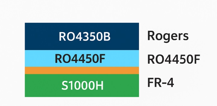
To balance performance and cost, designers often choose hybrid stack-ups — using Rogers materials (e.g. RO4350B, RO4003C) for RF layers, and FR-4 materials (e.g. S1000H, Nanya NPG, TUC TU-872)** for the rest.
While this hybrid approach is cost-effective, it brings significant manufacturing challenges.
Hybrid Lamination Overview

Fig.1 Rogers + FR-4 hybrid stack-up structure illustration
Typical material combinations include:
| RF Layer Material | FR-4 Material | Typical Applications |
|---|---|---|
| RO4350B + FR-4 | S1000H / Tg170 | 5G antenna, RF module |
| RO4003C + FR-4 | FR408HR / TU-872 | High-frequency control board |
| RO4835 + FR-4 | TU-768 / TUC-762 | Automotive radar, base station circuit |
The main challenge comes from differences in CTE (Coefficient of Thermal Expansion), resin flow, and lamination temperature between the two materials.
These must be carefully managed to avoid delamination, warpage, or impedance instability.
Key Process Parameters:
Lamination Temperature
Rogers materials such as RO4350B or RO4003C typically require 190–200°C lamination temperature.
FR-4 materials normally use 170–185°C.
The ideal compromise is 185–190°C for hybrid lamination.
Too high → FR-4 resin overflows excessively.
Too low → Rogers resin doesn’t flow enough → delamination risk.

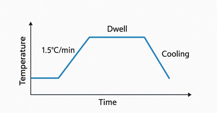
Fig.2 Typical lamination temperature profile for Rogers + FR-4 hybrid boards
Prepreg (PP) Selection
For Rogers-to-Rogers bonding, RO4450F prepreg is the standard choice to ensure dielectric consistency and adhesion.
For hybrid lamination, resin flow must be strictly controlled to prevent:
Excess flow: causes impedance deviation or resin intrusion into RF areas
Insufficient flow: results in voids or poor bonding
Recommended:
Use low-flow FR-4 prepreg (e.g., 2116 or 2113) when mixed with RO4450F to balance resin movement.
Surface Preparation
Rogers materials have a low surface energy and must be treated properly before lamination:
Plasma or oxide treatment for roughening
Pre-bake at 120°C for 2 hours to remove moisture
Skipping these steps often leads to delamination or voids after lamination.
CTE and Warpage Control
Typical Z-axis CTE:
RO4350B: ~32 ppm/°C
FR-4: ~55–65 ppm/°C
This difference can create internal stress during cooling, leading to warpage or layer separation.
Mitigation tips:
Maintain symmetrical stack-up (mirror structure top and bottom)
Avoid unbalanced copper distribution
Use slow and uniform cooling after pressing
Common Issues and Solutions
| Problem | Likely Cause | Solution |
|---|---|---|
| Delamination / Voids | Inadequate surface prep or moisture | Plasma cleaning + thorough baking |
| Excess resin flow | High-flow FR-4 PP or too high temperature | Use low-flow PP, reduce heating rate |
| Impedance drift | Resin intrusion or mismatched copper roughness | Control resin flow, match copper foil texture |
| Warpage | High CTE mismatch or asymmetrical stack-up | Symmetrical build-up, slow cooling |
| Layer separation | Improper lamination curve | Optimize heating curve (≈1.5°C/min ramp-up, stable dwell time) |
Example Process Data
Case: 8-layer RO4350B + S1000H hybrid board
| Parameter | Value |
|---|---|
| Total Thickness | 1.6 mm |
| Lamination Temperature | 188°C |
| Heating Rate | 1.5°C/min |
| Dwell Time | 70 min |
| Pressure | 2.0 MPa |
| Cooling | Slow cooling to<80°C before release |
| Surface Prep | Plasma + 120°C pre-bake for 2h |
This process effectively minimizes delamination and warpage, ensuring impedance stability and flatness.
Rogers + FR-4 hybrid lamination is one of the most critical and technically demanding processes in high-frequency PCB fabrication.
It allows excellent RF performance while reducing overall material cost — but success depends on deep understanding of materials, process control, and stack-up symmetry.
At iPCB, we have extensive experience in Rogers/FR-4 hybrid manufacturing.
Our engineering team optimizes lamination curves, prepreg selection, and impedance control to ensure the highest signal integrity and reliability for your high-frequency designs.