In specific applications, the essence of circuit board material selection is to select better technical indicators based on the data sheet. The key specifications (for example, dielectric constant Dk and dissipation factor Df) of two different PCB materials from different suppliers may look the same, which can make it difficult to decide.
For example, Rogers' high-frequency circuit board material RT 5880 and TACONIC TLY-5 have a Dk of 2.20 and a Df of 0.0009, which look the same. However, are the two PCB materials RT 5880 and TACONIC TLY-5 really close?Under what circumstances do data sheets for two completely different materials look the same?
When comparing different high-frequency circuit board materials, dielectric constant Dk and loss factor Df are the most common reference places. Both technical indicators are frequency-varying parameters. The dielectric constant Dk usually decreases with the increase of frequency, while the loss factor Df usually increases with the increase of frequency.
When comparing the dielectric constant Dk and loss factor Df of different circuit materials, especially when the circuit materials are from different PCB suppliers, pay attention to their frequency characteristics and compare them at the same frequency. This is true even for the same material tested at two different frequencies.
Not every circuit material is tested in the same way or under the same conditions, and differences in testing methods can result in differences in a material's key parameters (e.g., Dk and Df), even when evaluating the same circuit material. in this way.
Most PCB materials are anisotropic, meaning the same parameter has different values when measured in different directions. Taking Dk as an example, most circuit materials have different Dk values in the x-y plane than in the z-axis (thickness). Because the thickness of the dielectric material in the PCB provides the foundation and isolation for circuit traces and ground planes, circuit designers usually refer to the Dk of the PCB material as on the z-axis (material thickness).
It is possible for a circuit material supplier to provide Dk measurements for the material in both the x-y plane and the z-axis, but when comparing different materials, to ensure that the Dk measurement method used is the same, the comparison direction should be the same (Plane to plane, z-axis to z-axis).

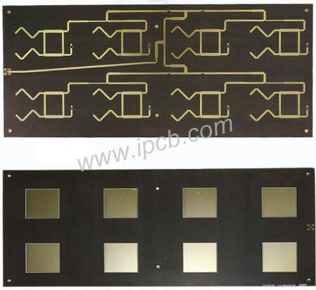
Rogers 5880 PCB
For most commercial PCB materials, Dk is also closely related to temperature. Although most circuit material Dk measurements are performed at room temperature (around +23ºC~+25ºC), even for the same material, a deviation of a few degrees above room temperature will cause the Dk measured value to be different from the measured value at room temperature. The graph below shows the effect of temperature on Dk measurements of PTFE/WG, RO3003 and RO3035 laminates.
Simply put, when comparing the Dk of different circuit materials from different suppliers, the Dk should be measured using the same test method in the same direction (z-axis) and at the same test frequency. To measure the Dk of circuit materials (e.g., RO3003, RO3035, RO3006, and RO3010), Rogers uses the IPC-TM-650 2.5.5.5 stripline method along the z-axis (thickness) of the material at 10 GHz and 23°C. direction to test. In the same way, when comparing the Df values of different materials, they should also be compared under similar conditions: z-axis direction, @10GHz and room temperature (approximately +23°C).
Asterisks or footnotes on data sheets are very important because they often alert the reader to anomalies or special circumstances. Due to the development of automotive safety systems and 5G wireless communication networks, the number of applications using millimeter wave frequencies is expected to continue to grow rapidly, and more and more circuit designers are considering selecting circuit materials suitable for higher frequencies (such as 60GHz and 77GHz) , while also weighing the trade-off between rolled copper foil and less smooth electrolytic (ED) copper foil.
At higher frequencies, rolled copper foil generally has lower losses than electrolytic (ED) copper foil. A key trade-off when using calendered copper foil on circuit materials is lower copper peel strength compared to electrolytic (ED) copper foil because the smooth copper surface compared to the rougher surface of electrolytic (ED) copper foil Improves the peel strength of copper. However, the copper peel strength of different circuit materials should not be compared only at 60GHz and 77GHz, any comparison should take these special circumstances into account. Comparisons of different circuit materials applied at millimeter wave frequencies should be made with respect to the peel strength achieved using the same type of copper foil. Not all circuit materials use the same type of copper foil for copper peel strength testing, and an asterisk or footnote in the specification in the data sheet may sometimes indicate that the copper foil is not the copper foil used when measuring copper peel strength.
For example, in the footnote [1] of the RT 5880 data sheet, it is mentioned that the dielectric constant is measured based on 1 oz electroplated copper foil using the IPC-TM-650 2.5.5.5 method at 10 GHz and 23°C. The test conditions for typical values of copper foil peel strength are after 1 oz electrolytic copper bleaching. In fact, Rogers' RT 5880 circuit board substrate can provide electrolytic copper and reverse copper from 8 to 70 μm. To meet higher power requirements, rolled copper can also be provided.

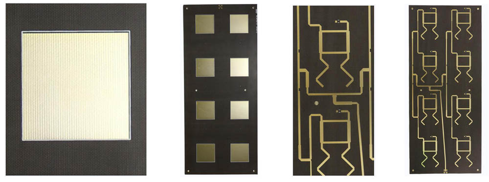
RT 5880 PCB
Thermal Conductivity of high frequency pcb
Another circuit material parameter to look at when comparing different materials is thermal conductivity. There are different testing methods for the thermal conductivity of circuit substrate materials, some use copper and some do not. Obviously, copper is a good conductor of heat, and the dielectric material of the high frequency circuit board material containing copper will affect the results in any thermal conductivity test, although the amount of this effect depends on the thickness of the dielectric material. Thin dielectric materials containing copper have higher thermal conductivity than thick dielectric materials containing copper.
Some might argue that the copper content is more like a conduit for the material's use in the actual application, with the copper traces on the material contributing to the overall thermal conductivity of the PCB material. However, most circuit simulation software assumes the thermal conductivity of the circuit material without copper when calculating the effect of a circuit material's thermal conductivity on the performance of circuits fabricated on that material.
It is obvious from the above several circuit material parameters that comparing different PCB materials from different suppliers may not be simple. When comparing data sheets for circuit materials, a good starting point is to ensure that the parameters being compared are the same—basic PCB material parameters such as Dk and Df are measured using the same test method at the same test frequency and temperature. Only by using the same test method to measure these parameters can we use these parameters to objectively and accurately compare different materials and effectively predict the performance of the final selected circuit material!
Based on the above, we can compare with the following points:
1.Compare at the same frequency
When comparing different high-frequency circuit board data, dielectric constant Dk and loss factor Df are the most common reference places. Both technical indicators are frequency-varying parameters. The dielectric constant Dk usually decreases with the increase of frequency, while the loss factor Df usually increases with the increase of frequency.
2.Compare under the same test method
Not every high-frequency circuit board material is tested in the same way or under the same conditions, and differences in testing methods will also lead to differences in the key parameters of the data (for example, Dk and Df).
3.Compare in the same direction
Most high-frequency circuit board materials are anisotropic, which means that the same parameter has different values when measured in different directions. Taking Dk as an example, most high-frequency circuit board materials have different Dk values on the x-y plane and the z-axis (thickness).
4.Compare at the same temperature
For most commercial high-frequency circuit board materials, Dk is also closely related to temperature. Although most high frequency circuit board data Dk measurements are performed at room temperature (around +23ºC~+25ºC), even for the same high-frequency circuit board data, a deviation of a few degrees above room temperature will cause the Dk measurement value to change. Different from the measured value at room temperature.
Taconic TLY-5 vs. Rogres 5880 High Frequency pcb Comparison It may not be simple to compare high frequency circuit boards from different suppliers. When comparing data sheets of high-frequency board data, a good starting point is to ensure that the parameters being compared are the same. Basic high-frequency board data parameters such as Dk and Df are measured using the same test method at the same test frequency and temperature. Only by using the same test method to measure these parameters can we use these parameters to objectively and accurately compare different high-frequency board data and effectively predict the performance of the final selected high-frequency board data!