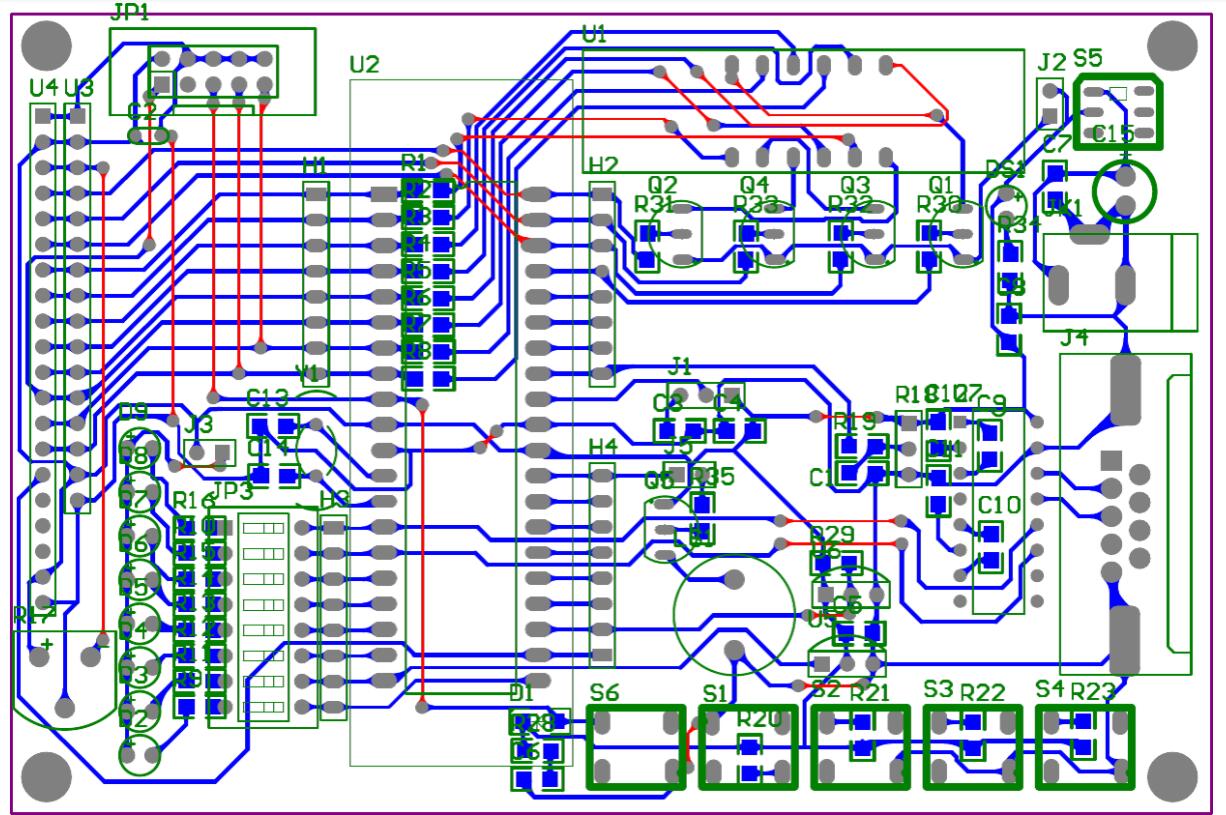
When talking about PCB circuit boards, the novice update will redesign the PCB schematic diagram and PCB design file, but the diagrams subtly refer to different things. Understanding the differences between them is a key to successful PCB manufacturing, so to make this a better first step, IPCB now breaks down the main differences between PCB schematics and PCB design.
What is a PCB circuit board?
Before getting into the difference between schematic and design, what you need to know is,what is a PCB? The circuit board is a green circuit board made of metal that connects all electrical circuit boards.
Therefore, the target still has subsequent design. Fix the various packaged components correctly on the circuit board, and connect the signals of each component of the device (through PCB connection capabilities). PCB processing requires engineers to provide Gerber files and turn the design into an actual circuit board (bare board without components installed). There are many well-known PCB processing factories in China. Components enable the PCB to function properly. Without it, the electronics will not work.
PCB schematics and PCB design
A PCB schematic is a simple two-dimensional circuit of different designs with many component functions and connectivity.
Therefore, PCB schematic is the first part of designing a printed circuit board. Connection method. As the name suggests, a PCB schematic is a plan and blueprint. It does not specify where the components are located. Instead, the schematic outlines how the PCB will ultimately be connected and forms a key part of the planning process.
After the blueprint is completed, the next step is PCB design. A design is the layout or physical representation of a PCB schematic, including a layout of copper traces and holes.
PCB design is a performance-related phase. , but it’s not easy to understand its functionality by looking at the original image.
After completing these two stages and you are satisfied with the performance of the PCB, you need to go through the manufacturer to implement it.

PCB circuit board schematic elements
Now that we know the difference in contacts, let’s take a closer look at the PCB key points of the schematic.Like we said,it's all there to see, but there are a few things to keep in mind.
In order to be able to clearly see the connection, not more proportions are created. In PCB design,it's probably very close. It is impossible to connect to each other and cross each other.
Some links may be on the other side of the map and have a marker indicating they are linked.
This PCB "schematic" can take one, two or even several pages to describe everything that needs to be included in the design.It is important to note that more complex schematic diagrams can be arranged as functional diagrams to improve individuality.
Circuit board design elements
It's time to delve deeper into the elements of PCB design files.In stages,everything from hand-drawn blueprints is now as simple as physical representations built using laminated or ceramic materials.Use Light Painting PCB.
The content of the PCB design file follows the blueprint of the schematic process flow, but is not the same and is built in many different ways.
When we always project PCB model design files, what we project in 3D is 3D, including circuit boards and design files. Because it can be single layer or fine, but the most common is two layers.
We can observe some differences between PCB drawings and PCB design files.
All components are correctly sized and positioned.
If two points shouldn't,then you have to separate yourself or switch to another PCB layer, thus avoiding crossing over each other.
Therefore,we briefly illustrate the actual performance of the PCB design since native verification is a later stage of the final product. Physical requirements.
Nearly all manner of components allow for connector current and temperature related issues near distribution boundaries, and the various traces must be more...
Because physical limitations and requirements mark PCB design files that often look much different than the design on the schematic, the design file includes a screen-printed layer. Use a circuit board.
All the parts need to be assembled onto the PCB and then work as planned. If not, you need to re-render.
The circuit schematic diagram is a representation pipeline used to show the working principle of the equipment's electricity, the role of each electrical component, and the relationship between each other. Using the methods and techniques of electrical schematic diagrams is very beneficial for analyzing power lines and troubleshooting machine tool circuit faults. Electric power schematic diagram generally consists of main circuit, control circuit, protection, distribution circuit and other parts.
Although PCB schematics and PCB design files are often restored, but rarely, making PCB schematics and PCB design refer to two separate processes when making printed circuit boards. A PCB schematic diagram that can draw the process flow must be created first before PCB design can be carried out, and PCB design is an important equipment that determines PCB performance and intellectual property rights.
The design of the circuit board is based on the pcb schematic diagram to achieve the functions required by the circuit designer. The design of the circuit board mainly refers to the layout design, and the layout of external connections needs to be considered. Optimized layout of internal electronic components. Optimized layout of metal connections and vias. Electromagnetic protection. heat dissipation and other factors. Excellent circuit board design can save production costs and achieve good circuit performance and heat dissipation performance. .