In PCB SMT (Surface Mount Technology) process, PCB board SMT Patch Points Counts are key indicators for production management and process evaluation. Unlike simply calculating component or packaging types, PCB SMT Patch Points Counts are typically measured during each soldering operation and reflect the actual workload of the surface mount machine. This not only affects production planning, but also serves as the basis for evaluating production capacity, programming efficiency, and equipment load.
The Importance of Calculate the number of PCB board SMT Patch Points Counts:
1. Equipment Configuration: Accurately Matching Capacity with Product Characteristics
For products with a high number of PCB SMT (Surface Mount Technology) patch points counts, priority should be given to high-performance placement machines. For instance, the Samsung SM482. These machines are equipped with multiple placement heads and high-speed feeding systems, capable of producing over 30,000 points per hour, ensuring stable production capacity. For products containing densely packed small components, high-resolution inspection equipment should be used. For example, the Yamaha YSM40R, with its megapixel vision system and multi-angle illumination technology, ensures inspection and placement accuracy to ±0.01 millimeters, effectively reducing misalignment. Furthermore, creating a classification matrix to match equipment capabilities with product mix helps allocate resources precisely and avoid mismatch or waste of production line resources.
2. Production Planning: Optimizing Process Rhythm Based on PCB SMT Patch Points Counts:
In production planning, grouping orders with similar smt patch points counts (maximum difference of 500 points) can significantly reduce line changeover time. Line changeovers take an average of 30 to 60 minutes, and consolidating these orders helps improve capacity utilization. If the number of solder joints varies significantly between orders, they should be allocated accordingly to ensure 70% to 80% production line utilization, avoiding resource waste or overload. Real-time scheduling and counting analysis within the MES system can dynamically adjust task sequencing to keep daily production capacity fluctuations within 5%, ensuring stable cycle times and improving efficiency.
3. Quality Control: Targeted Inspection of High-Risk Areas
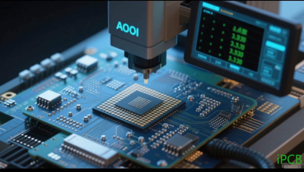
For areas with a high number of smt patch points (e.g., multiple BGAs placed side by side), AOI inspection paths must be planned in advance. Multi-angle scanning should be used to ensure complete solder joint identification. For non-visible solder joints such as BGAs, comprehensive X-ray inspection is required to ensure 100% coverage.

AOI inspection equipment for BGA area inspection scene
Basic Calculation Methods for Common PCB board SMT Patch Points Counts:
1. Standard SMT components (resistors, capacitors, inductors, etc.): Each component counts 1 dot.
IC components (SOP, QFP, BGA, etc.): Calculated by the number of pins, typically 1 dot for every 2 pins (e.g., a QFP-48 package counts 24 dots).
2. Special-shaped components (connectors, large electrolytic capacitors, etc.): Depending on complexity, 2-5 dots may be counted, determined by factory standards.
Counting Counts for Special Cases
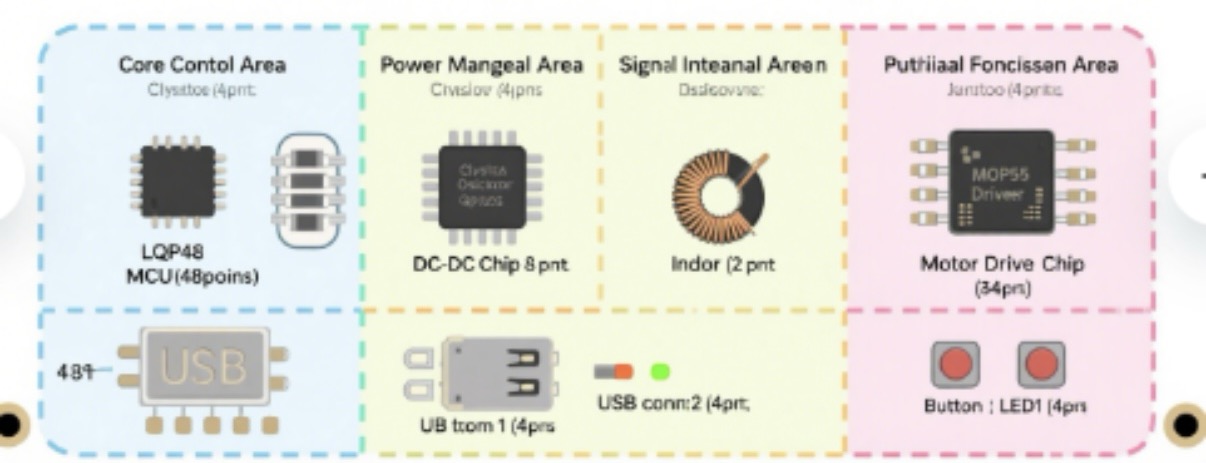
3. Double-Sided SMT: The SMT counts for both sides of the PCB are calculated separately and then added together. For example: 300 dots for the front and 150 dots for the back, for a total of 450 dots.
4. Panelization: If the PCB uses a panelization design, the total dot count equal the Number of dots per board × Number of panels.
5. Repairs or replacements: Generally not counted, but if secondary SMT is involved, they may be counted additionally.


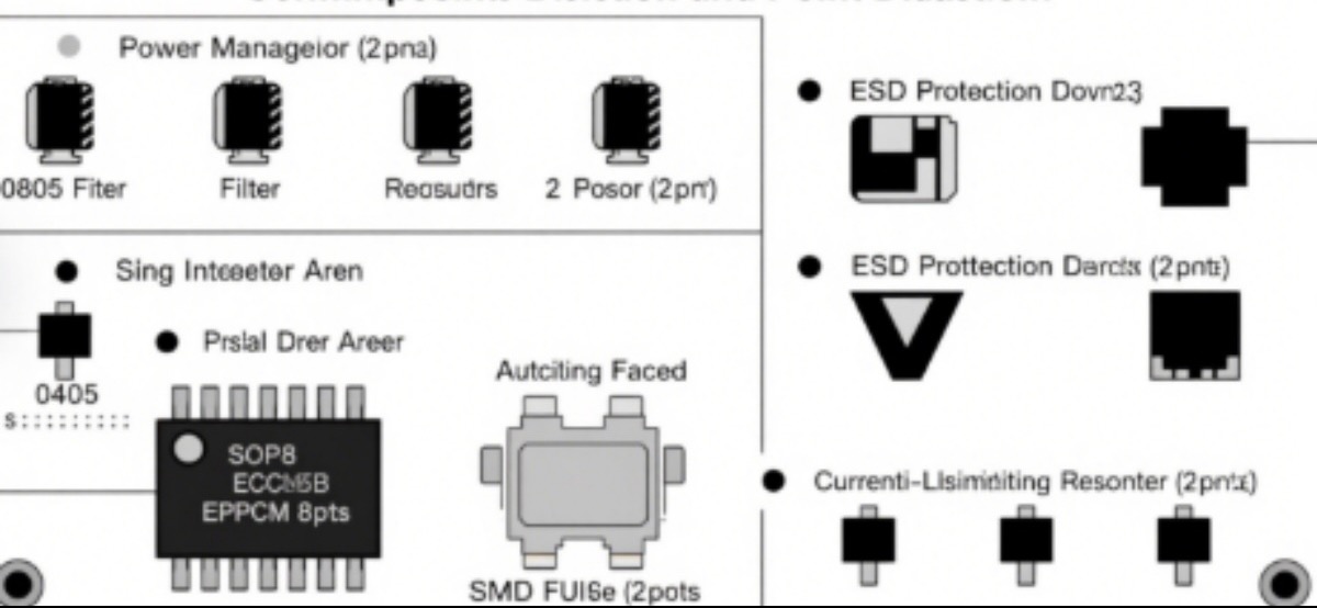
Double-sided circuit board point distribution diagram (front/back mounting)
Factors influencing the calculation of PCB board SMT Patch Points Pounts.
Although there are standards to follow for point calculation, actual production is also affected by the following factors:
1. Component packaging complexity
Fine-pitch components (such as 0.4mm Pitch QFP) take longer to manufacture than conventional components, and some factories will increase the weighting of the number of points.
Special components (such as large-sized inductors and shielding cases) may require additional adjustments to the suction nozzle or mounting speed, and the count of points may be higher.
2. Mounter efficiency
High-speed machines (such as Fuji NXT) are suitable for high-density placement of small components, and the calculation of points may be more stringent.
Multifunction machines (such as Siemens Siplace) are suitable for complex components, but the calculation of points may be adjusted due to increased adjustment time.
3. Process requirements
High precision requirements (such as in medical and automotive electronics) may affect the calculation of points, and some factories will add extra points.
Whether optical inspection (AOI/SPI) is required is usually not counted towards the number of points, but it will affect the overall production time.
How to optimize the number of PCB SMT Patch Points Pounts?
Although point counting is a standard on the production side, the design side can also be optimized to reduce points and improve production efficiency.
1. Prioritize the use of standard packages: Optimize for standard packages like 0402 and 0603, and minimize the mixing of special specifications.
2. Control the quantity of non-standard components: Prioritize the selection of standard devices to reduce the increase in points caused by non-standard components.
3. Optimize layout density: Reduce high-density areas to avoid frequent material changes for the pick-and-place machine, which is conducive to improving the pick-and-place rhythm.
4. Reasonable panel design: Control the panel structure to facilitate continuous operation of the pick-and-place machine and improve board loading efficiency.
Guide to Avoiding Pitfalls in PCB SMT Patch Points Pounts Calculation.
1. The number of points does not equal the number of components
The point count of a 16-pin IC is 16, not 1. The point count of 10 0603 resistors is 20 (2 points per resistor), not 10. Confusing concepts may lead to errors in capacity assessment.
2. Clarify whether the fixed foot is counted towards the points
The fixed feet that require welding are counted towards the points, while those that are only mechanically positioned (without welding) are not counted towards the points.
3. Processing of virtual pads
Test pads without electrical connections are not counted towards the point count; pads for temporarily soldered probes are also not counted towards the regular point count.
Mastering the calculation standards for PCB board SMT Patch Points Pounts not only meets the basic requirements of process specifications but also serves as a crucial foundation for achieving efficient production management. From reasonable estimation during front-end design to standardized execution in the back-end processing, precision and rigor in every step ultimately manifest as reliable product quality and continuous improvement in overall production capacity.