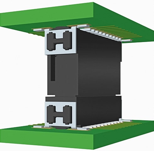
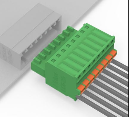
What is a PCB connector? A PCB connector (Printed Circuit Board Connector) is an electronic component used to connect electronic devices on a circuit board to external circuits. PCB connectors are widely used in electronic products, such as computers, mobile phones, televisions, cars and other electronic devices. It can connect and disconnect the circuit connection between the circuit board and other electronic components by plugging and unplugging.
The main functions of PCB connectors include: interconnection between circuit boards, simplify equipment assembly and maintenance, provide modular design possibilities, and adapt to the use requirements under different environmental conditions. In modern electronic products, from smartphones to industrial control systems, almost all electronic devices rely on various types of PCB connectors to realize their functions.

PCB connector
Common PCB connector types and features
1. Board-to-Board Connectors
Board-to-Board connectors are specifically used to connect two PCB boards and can be divided into several sub-types:
Pin Header and Socket Connector is the most basic type, consisting of one or more rows of metal pins and corresponding sockets. The common spacing is 2.54mm, 2.0mm, 1.27mm, etc., and the number of pins ranges from a few to hundreds. This type of connector is low-cost and easy to use, but the connection strength is average, and it is suitable for occasions where mechanical strength is not required.
Mezzanine Connector is designed for parallel stacked PCBs to provide high-density interconnection. The typical spacing is 0.8mm or less, which can support high-speed signal transmission and is widely used in communication equipment and high-end computing equipment.
Card Edge Connector directly inserts the edge of the PCB board into the connector and realizes electrical connection through the spring contacts in the connector. This design saves space and is low in cost. It is common in early memory modules and expansion cards.
2. Wire-to-Board Connectors
Wire-to-board connectors are used to connect wires or cables to PCBs. The main types include:
IDC connectors (Insulation Displacement Connectors) achieve connection by piercing the insulation layer of the wire through specially designed metal contacts, without pre-stripping the wire, which greatly improves production efficiency. Commonly used in ribbon cable connections, such as hard disk data cables.
Crimp connectors require the metal terminals to be crimped onto the cable before being inserted into the connector housing. This connection method has high reliability and good vibration resistance, and is suitable for automotive and industrial environments.
Screw terminal block connectors fix the wires with screws, allowing on-site wiring and firm connections, and are commonly used in power connections and control signal connections.
3. Socket connectors
Socket connectors are used for the installation of pluggable components, mainly including:
IC sockets allow integrated circuit chips to be connected to PCBs without direct soldering, which facilitates chip replacement and upgrading. There are many packaging forms such as DIP, PLCC, PGA, etc.
SIM card sockets are designed specifically for SIM cards, with a compact structure and reliable contact performance to ensure good connections in mobile environments.
Memory card sockets support the insertion and removal of various memory cards such as SD, MicroSD, CF, etc., and are widely used in consumer electronics products.
4. Special-purpose connectors
RF connectors such as SMA and BNC are used for high-frequency signal transmission, with precise impedance control and shielding design to ensure signal integrity.
Fiber optic connectors include LC, SC, ST and other types, which are used for optical signal transmission and have extremely high bandwidth and anti-interference capabilities.
Waterproof connectors use special sealing design to prevent moisture and dust intrusion, and are suitable for outdoor equipment and industrial environments.

Precautions for installation and use of PCB connectors
1. PCB design considerations
The pad design must match the connector specifications, especially for high-density connectors. Slight deviations may lead to poor soldering.
The installation position should consider the plug-in and unplug operation space and stress distribution, and avoid installation in the PCB's easy-to-bend area.
In addition to welding, additional mechanical fixation may be required, such as screws or buckles, especially for large connectors.
2. Welding process
Temperature curve control is critical, especially for plastic shell connectors, overheating may cause deformation.
The amount of solder should be appropriate. Too little leads to insufficient strength, and too much may cause short circuits or affect plugging.
Time and temperature should be controlled during manual soldering to avoid heat damage to the connector.
3. Use and Maintenance
The plugging and unplugging operation should be kept straight to avoid skew and damage to the terminal. For the lock design, it must be unlocked before unplugging.
Cleaning and maintenance should use appropriate methods to avoid corrosive cleaning agents from damaging the contact surface.
Check the connection status regularly, especially for applications in vibration environments, to detect looseness or corrosion problems early.
As the "bridge" of the electronic system, the selection and application of PCB connectors directly affect the performance and reliability of the entire device. With the advancement of technology, the types and functions of connectors are constantly enriched. Designers need to consider electrical performance, mechanical characteristics, environmental adaptability and cost factors according to specific application requirements to select the most suitable connection solution.