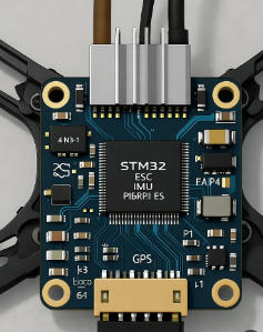
A drone soars freely through the sky. Behind its graceful flight, a circuit board quietly pulses. Imagine this: as the propellers spin at high speed, catching the wind, the tiny circuits on the circuit board instantly process sensor signals and precisely control the motors. This circuit board is more than just a collection of electronic components; it's the drone's "nervous system."
First, let's gain an intuitive understanding of the specific role of a circuit board. To ensure stable flight, it must evenly distribute battery power and analyze data from gyroscopes and accelerometers in real time. For example, in a quadcopter, a four-rotor drone, the circuit board acts as the flight controller, driving the PID control algorithm. Even the slightest deviation in control can cause the aircraft to tilt and risk crashing. Personally, when I first encountered circuit boards, simply measuring voltage with a multimeter gave me a thrill. It's incredible to think that this tiny green circuit board could keep a drone weighing only a few hundred grams aloft. In fact, in commercial drones, PCBs support camera video transmission and GPS tracking, and are used for agricultural monitoring and disaster relief. I've seen many projects fail due to PCB design errors, and the lesson I learned is that PCBs are crucial to drone reliability.
Let's break down the basic structure of a PCB. Starting with the simplest single-layer PCB, a circuit board with only one copper conductor is ideal for beginners building small drones. Since components are mounted on only one side, soldering is easy. However, signal interference is a drawback. Next, let's look at a two-layer PCB. The top and bottom layers of the PCB intertwine, allowing for efficient placement of complex circuits. For example, distributing the ESC (electronic speed controller) for motor control on both sides reduces heat generation. Furthermore, multi-layer PCBs with four or more layers can increase density. Industrial drones use high-frequency multi-layer boards such as Rogers materials to minimize noise. Flexible PCBs (Flex PCBs) are also attractive. This flexible material allows them to bend and conform to the curves of the aircraft, reducing weight by nearly 10%. In my project, I used a Flex PCB to embed sensors into the narrow space inside the propeller shroud to enhance collision detection. The choice of this structure depends on the drone's intended use. For small racing drones, a lightweight single-chip design is recommended; for surveillance drones, a durable multi-chip design is recommended.

circuit board
Let's walk through the design process firsthand. First, choose the software. KiCad is free and open source, allowing even beginners to intuitively draw circuit diagrams. Altium Designer is professional-grade software that excels at 3D simulation. Eagle, also owned by Autodesk, offers convenient cloud integration. Step 1: Define your requirements. Determine the drone's dimensions (e.g., a 55mm chassis) and features (e.g., built-in GPS?), and create a parts list. Step 2: Create a schematic. Virtually place components and draw connections. Here, thicken the power lines and route them in a star pattern to prevent noise. Step 3: Create the PCB layout. Use online tools like EasyEDA to arrange the components symmetrically. Place the IMU in the center and the MOSFETs close to the motors. Add curved edges for increased durability and define a 10x10cm outer frame. Step 4: Use DRC (Design Rule Check) to detect errors. Set trace widths to 0.5 mm or larger and use vias to check interlayer connections. I personally made the mistake of using too thin traces in my initial design, which caused overheating and nearly melted the board. Since then, I've never skipped thermal simulations. Step 5: Export Gerber files.
I still remember the clever tricks I employed to address thermal management challenges. Due to heat generated by the ESCs, the drone's circuit board temperature could easily exceed 60°C and degrade during long flights. To address this, I used FR-4 material with high thermal conductivity and made extensive use of thermal vias. I also added a heat sink for air cooling. Metal core printed circuit boards (MCPCBs) are very effective for high-power motors. The copper base dissipates heat quickly. Signal integrity is also crucial, maintaining 50Ω impedance matching for high-speed signal lines. Furthermore, the board is conformal coated to prevent vibration. In my project, this improved the board's rain resistance by 20%. To reduce noise, we inserted ferrite beads into the power lines. Small details like these can extend the life of the board and improve its reliability. If you are interested in our circuit board design services, please contact us.