A Power Amplifier is one device that can make "something" become bigger. It is similar to a magnifying glass. So what does it magnify? It usually magnifies Current or Voltage as shown in the photo below:
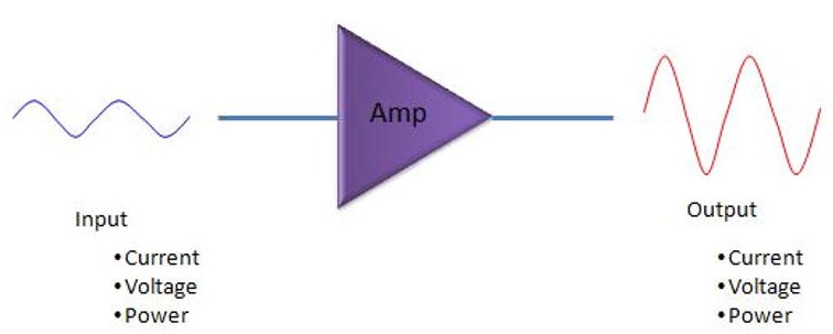
The function of Power Amplifier
The types of RF Power Amplifier
It seems hard to find a product that uses Amplifier as a single component, as experienced engineers who have used discrete amplifiers in their designs are becoming fewer and fewer. In most products, especially in mobile communication products, most of the amplifiers have been integrated into Radio Frequency IC (RF IC). But there are still some special situations, such as the examples listed in the photo. These are discrete amplifiers, which are independent and non-integrated amplifiers, and are usually used at the final Stage of the transmitter chain (a-e). Because the final Stage PA will make too much heat when it works, the heat can't be dissipated, which will damage the IC, so it should use an independent component – a discrete amplifier to achieve.
Although most amplifiers have been integrated into chips, in some high-power transmission applications — such as telecom repeaters and various base stations in mobile communication systems — discrete amplifiers or modules built around pairs of discrete amplifiers (as shown in examples (f) to (k)) are still used. This is because these applications require very high power, which makes full integration impractical.
In recent years, even high-power amplifiers have become more intelligent. They're no longer just simple amplifiers — now they integrate control circuits and network interfaces (like Ethernet), allowing them to be installed right next to the antenna on top of base station towers. These "smart" amplifiers function more like compact amplifier systems and are commonly known as Remote Radio Heads (RRH). They help reduce signal loss and improve efficiency, making them a key component in modern mobile communication systems.
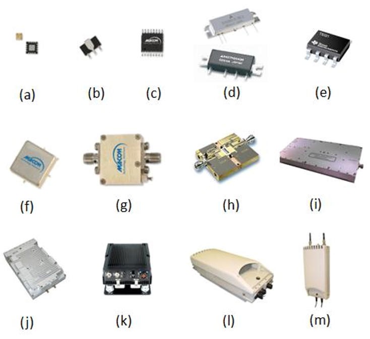
Photograph of a power amplifier unit
An ideal amplifier is simple—it just amplifies the input signal by a fixed ratio. For example, if the input is a certain value, the output is that value multiplied by a constant (like 2 times or 3 times). This ideal behavior is shown as a blue straight line in the graph. However, in reality, amplifiers don't always perform perfectly. They work close to ideal within some ranges, but at certain points, the output starts to deviate and doesn't scale proportionally anymore, showing nonlinear behavior. This real-world behavior is shown as a red curve in the graph. This curve is more complex than a straight line and can be described using polynomials. Simply put, an ideal amplifier amplifies linearly, while a real amplifier sometimes "distorts" and the output isn't as predictable.
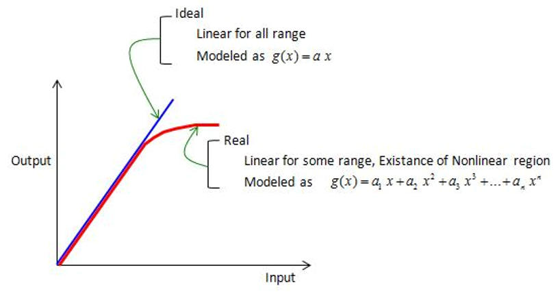
Comparison of Typical Characteristics Between Ideal and Real Amplifiers
Why do nonlinear problems arise?
The nonlinear parts of an amplifier are important because when a simple sine wave signal passes through a nonlinear amplifier, the output contains many extra frequencies that were not present in the original signal—like unwanted noise mixed into a clean sound. These additional frequencies interfere with signal quality and cause problems. If you don't want to calculate it yourself, you can use online tools to help. The key point is to understand that nonlinear amplifiers produce these unwanted extra frequencies, which are undesirable.
Nonlinear equation 1
Using graphs makes it easier to understand. The first row of the graph shows the ideal operation of the amplifier, while the last row displays the effects after including second- and third-order nonlinearities, where two extra frequency peaks—absent in the input signal—appear in the output. The second and third rows separately show the impact of the second- and third-order nonlinearities, helping to clearly illustrate how these additional frequencies are generated.
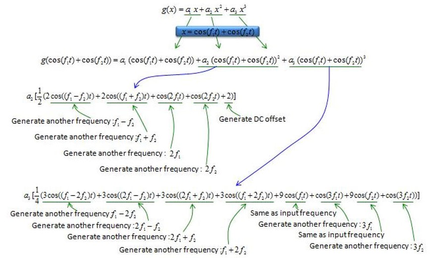
Nonlinear equation 2
How do extra frequencies appear?
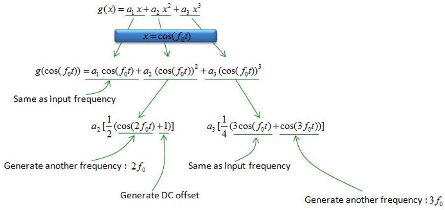
This can be seen by plotting the related mathematical formulas. When testing an amplifier, it's important to accurately identify the frequency peaks caused by nonlinearity. When measuring with a spectrum analyzer, many peaks often appear in the output that were not present in the input signal. Some of these peaks are caused by the amplifier's nonlinearity, while others come from different sources. Understanding the characteristics of nonlinearity helps distinguish these unwanted frequencies and find their true origins.
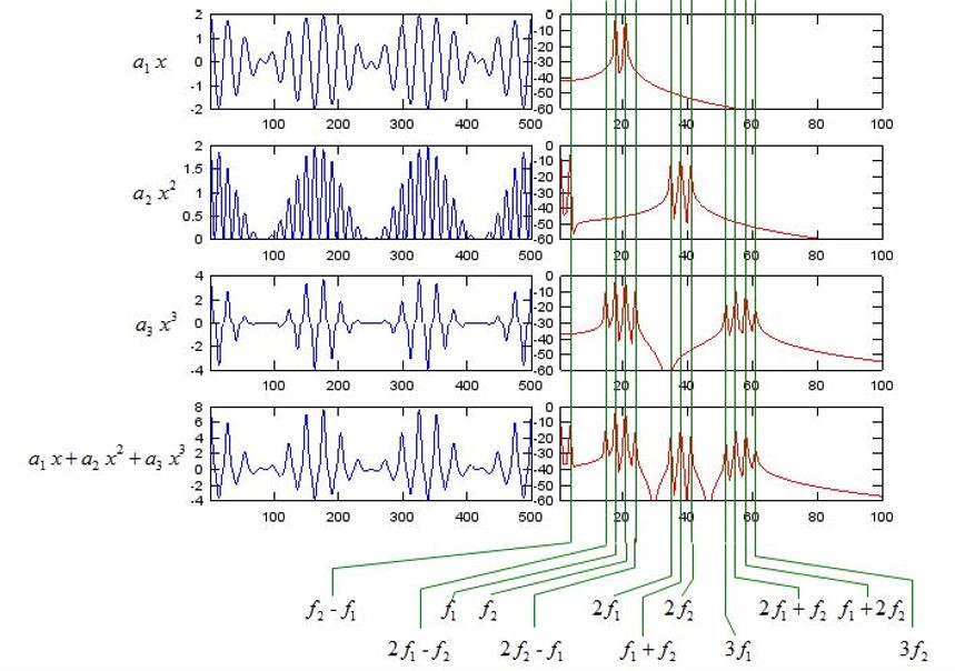
Illustration of the process of generating extra frequencies
When the amplifier input is a narrowband or continuous wave signal, nonlinearity causes extra frequencies to appear. However, in most cases, the input is a wideband modulated signal, and the most noticeable effect of nonlinearity is increased interference with adjacent channels, shown as degraded ACLR or ACPR, which in turn affects signal quality and spectrum efficiency.
How is nonlinearity represented?
Nonlinearity in amplifiers is generally undesirable and, although it cannot be completely eliminated, efforts are made to minimize it. To measure and control these nonlinearities, certain parameters are used to describe them and are included in the amplifier's datasheet. The two most common parameters are the Third-Order Intercept Point (IP3) and the 1 dB Compression Point, which help indicate the level of nonlinearity and the amplifier's performance.
How to avoid nonlinear effects?
Although it is impossible to completely eliminate this issue, there are various methods to reduce it. Some common techniques are as follows:
1. Replace the amplifier
Use an amplifier with a wider linear range to reduce nonlinearity. However, this usually increases cost, and in some cases, such components may not even exist.
2. Lower the signal power
Reduce the signal power so the amplifier operates within its linear region. But if the signal amplitude is too large and there isn't enough margin to reduce it, this method won't work.
3. Add filters
Allow the amplifier to produce all the unwanted nonlinear distortion, then use extra filters to remove those unwanted frequency components. This also increases cost and finding suitable filters that can handle high-power amplified signals can be challenging.
4. Digital predistortion (DPD)
A newer technique applied in advanced applications. It uses intelligent algorithms to pre-compensate for the amplifier's nonlinearity and reduce distortion. However, designing the right predistortion algorithm is complex.
In summary, each method to avoid nonlinearity has its pros and cons, and the appropriate solution depends on the specific situation.
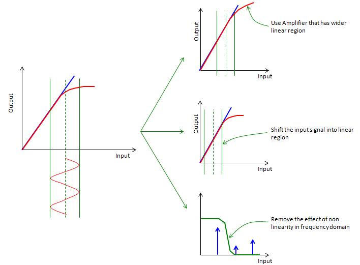
Three solutions
Gain and efficiency
The amplifier's function is to take a weak input signal and turn it into a much stronger output signal—in other words, it amplifies the energy. This extra energy doesn't come from nowhere; it is supplied by an external power source, usually labeled "Vdd" in circuit diagrams. For example, in a mobile phone, Vdd is connected to the battery, while in larger systems like base stations, Vdd is connected to an external power supply.
Gain indicates how much an amplifier increases the input signal—it's the ratio of output power to input power and shows the level of amplification. Efficiency refers to how much energy the amplifier uses to achieve that amplification. For example, if two amplifiers provide the same gain but one requires less voltage and current to do so, it is considered more efficient. An amplifier with low efficiency wastes more energy, and that wasted energy is usually released as heat, causing the device to heat up.
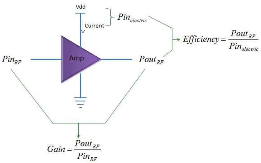
Definition of Power Amplifier Gain