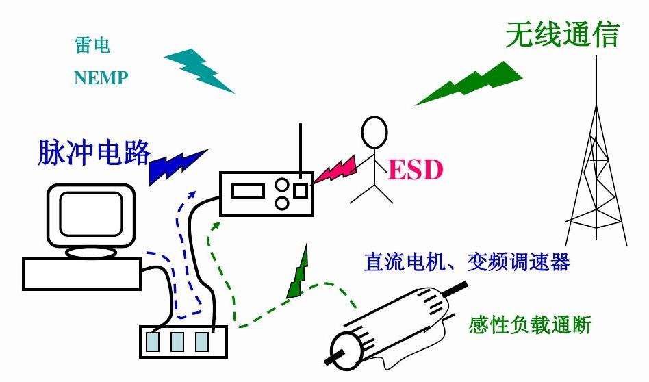
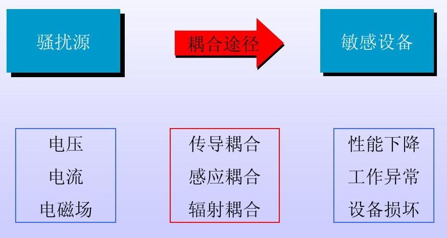
Electromagnetic compatibility refers to the electronic equipment in a variety of electromagnetic environment to co-ordinate the ability to work effectively, the purpose is to make the electronic equipment can not only inhibit a variety of external interference,so that the electronic equipment in a particular electromagnetic environment can work normally, but also to reduce the electronic equipment itself on other electronic equipment electromagnetic interference.Here,EMC includes two aspects of the requirements: on the one hand, it refers to the normal operation of the equipment in the process of the environment generated by the electromagnetic interference can not exceed a certain limit; on the other hand, it refers to the apparatus of the environment in which there is a certain degree of electromagnetic interference with the degree of resistance to interference, that is, electromagnetic sensitivity.
In the International Electromagnetic Commission standard IEC definition of electromagnetic compatibility: the system or equipment in the electromagnetic environment can work normally, and will not cause interference to other systems and equipment.
EMC includes EMI (Electromagnetic Interference) and EMS (Electromagnetic Survivability). The so-called EMI (Electromagnetic Interference) is the electromagnetic noise generated by the machine itself in the process of performing its function that is unfavourable to the other systems; and EMS refers to the ability of the machine to be unaffected by the surrounding electromagnetic environment in the process of performing its function.
Electro Magnetic Compatibility (EMC) The ability of various electrical or electronic equipment to function properly in a common space with a complex electromagnetic environment and to meet design requirements with a specified safety factor. Also known as Electromagnetic Compatibility.
The meaning of electromagnetic compatibility includes:
1.Mutual consideration between electronic systems or equipment in the electromagnetic environment;
2.The ability of an electronic system or equipment to function properly in a natural electromagnetic environment in accordance with design requirements.If extended to the impact of the electromagnetic field on the ecological environment, then the electromagnetic compatibility of the contents of the discipline can be called environmental electromagnetism.
Electromagnetic compatibility research is with the electronic technology gradually to high-frequency, high-speed, high-precision,high-reliability,high sensitivity,high-density (miniaturisation, large-scale integration), high-power, small-signal use, complexity and other aspects of the need for the gradual development. Especially in the artificial Earth satellites, missiles,computers,communications equipment and submarines in the large number of modern electronic technology, so that the electromagnetic compatibility problem is more prominent.

electromagnetic interference
Internal interference refers to the mutual interference between the internal components of electronic equipment, including the following types:
1.Interference caused by leakage of the operating power supply through the distribution capacitance and insulation resistance of the circuit. Related to the operating frequency.
2.Interference caused by mutual coupling of signals through the impedance of ground, power and transmission lines, or mutual inductance between lines.
3.The interference caused by the heating of some components inside the equipment or system, which affects the stability of the components themselves or other components.
4.Interference caused by magnetic and electric fields generated by high-power and high-voltage components affecting other components through coupling.
External interference refers to the electronic equipment or system outside the factors on the line,equipment or system interference, including the following:
1.External high voltage, power leakage through the insulation and interference with electronic circuits,equipment or systems.
2.External high-power equipment generates a strong magnetic field in space,which interferes with electronic circuits,equipment or systems through mutual inductive coupling.
3.Space electromagnetic waves on the electronic circuit or system interference.
4.The unstable temperature of the working environment causes the interference caused by the change of the parameters of the electronic circuits, equipment or internal electronic components of the system.
5.Interference caused by equipment powered by the industrial power grid and by grid voltage passing through power transformers.

Three Elements of Electromagnetic Compatibility
Electromagnetic compatibility
EMC: (Electromagnetic compatibility) Electromagnetic compatibility
EMI: (Electromagnetic interference) electromagnetic interference
EMS: (Electromagnetic Susceptibility) electromagnetic sensitivity
RE: (Radiated emission) Radiation disturbance (commonly known as: electromagnetic radiation, radiation emission)
CE: (Conducted emission) Conducted disturbance (commonly known as: conducted emission)
CS: (Conducted Susceptibility) Conducted Harassment Resistivity
RS: (Radiated Susceptibility) Radiofrequency Electromagnetic Field Radiation Resistance
ESD: (Electrostatic discharge) Electrostatic Discharge
EFT/Burst: (Electrical fast transient burst) electrical fast transient pulse group
RFI: (Radio Frequency Interference) Radio Frequency Interference
ISM: (Industrial Scientific Medical) industrial, scientific, medical use of radio frequency equipment
How to control electromagnetic compatibility during PCB design?
1.Choose a reasonable line width PCB transient current impact interference is mainly caused by the inductance of the PCB circuit, so should try to reduce the inductance of the PCB circuit.
2.Using the correct layout strategy using equal linear conductor inductance can be reduced, but the mutual inductance between the conductor and the distribution capacitance will be added, in the layout allows, it is best to use a good zigzag structure network wiring, the specific side of the method of PCB wiring, the other side of the perpendicular wiring, and then in the intersection of the holes with the metallisation of holes connected.
3.In order to inhibit cross-pollution between PCB conductors, in the wiring design to avoid long-distance isometric wiring, as far as possible to open the distance between the wires, signal lines, ground and power lines do not cross. The wires should be spaced as far apart as possible, and signal lines, ground lines and power lines should not be crossed. Crosstalk can be effectively suppressed by placing a printed line between some signal lines that are very sensitive to interference.