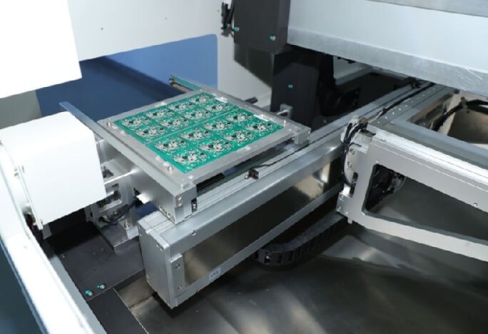
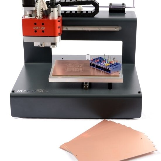
Milling pcb board refers to the process of physically cutting, separating, or slotting printed circuit boards (PCBs) using a high-speed rotating cutting tool on a CNC milling machine or engraving machine. Compared to traditional die cutting or V-cut processes, milling is more flexible and suitable for a variety of complex and precise PCB structures.
It not only segments the contours of finished boards but also performs various operations such as drilling holes, slotting, and chamfering. It is an indispensable process in modern high-precision PCB manufacturing.

milling pcb board
Key concepts and principles related to milling include tool direction, milling compensation, and positioning methods.
1.Tool Direction
When the milling cutter enters the board, one surface is always facing the milling cutter's cutting edge, while the other surface is always facing away from the milling cutter's cutting edge. The former results in a smoother surface with higher dimensional accuracy. The spindle always rotates in a clockwise direction. Therefore, whether using a CNC milling machine with a fixed spindle and a moving table or a fixed table and a moving spindle, when milling the outer contour of a printed circuit board, the tool path should be moved counterclockwise.
This is commonly known as up-cut milling. Climb milling is used when milling frames or slots inside the circuit board. Milling compensation automatically offsets the milling cutter from the center of the milling path by half the set cutter diameter, or the radius, according to the set value, to ensure that the milled contour matches the programmed setting. If the machine tool has a compensation function, it is important to pay attention to the compensation direction and program commands. Incorrectly using the compensation command can cause the circuit board contour to increase or decrease by an amount equal to the cutter diameter.
2. Milling Compensation
Since the milling cutter has a certain diameter, tool radius compensation is required to ensure that the actual machining contour matches the design.
For external contour milling: the tool path should deviate outward by one tool radius;
For internal hole or slot milling: the tool path should be offset inward by the radius.
Modern CAM software can automatically calculate the compensation path, but the operator still needs to set the tool parameters and calibrate the program to ensure accurate compensation.
3. Positioning Methods (PCB Positioning)
Precise board positioning is a prerequisite for high-quality milling. Common positioning methods include:
Mechanical positioning holes: Use alignment holes and locating pins to ensure consistent X/Y positioning;
Optical positioning: Uses a camera to identify mark points, suitable for high-precision requirements;
Frame positioning or vacuum suction: Suitable for large or irregular boards.
Different positioning methods are suitable for different production lines and processing precision requirements. Choosing the right method can significantly improve processing consistency.
Advantages and Limitations of Milling PCBs
Advantages:
High precision: Suitable for complex contours and high-quality surface finishes;
No plate etching required: Suitable for rapid prototyping and small-batch production of multiple products;
Flexible processing: Supports a variety of materials, including FR4, aluminum substrates, and rigid-flex boards;
Pollution-free process: Environmentally friendly, especially for trace metal processing;
Limitations:
Lower processing efficiency than stamping: Unsuitable for ultra-large-scale production;
Tool wear: Especially during high-speed, high-frequency processing;
Burst and dust generation: Requires additional processing;
High equipment investment: High-precision CNC equipment is expensive;

milling pcb board
Practical Example of milling pcb board:
A customer was producing a special-shaped aluminum-based LED light panel, and traditional stamping was unable to meet the required surface precision. PCB milling achieved:
Processing accuracy improved to ±0.05mm;
Smooth cutting edges, eliminating the need for post-processing;
Processing time per sheet kept under 5 seconds;
Product qualification rate increased from 90% to over 98%;
This demonstrates that milling is a cost-effective solution for small- to medium-volume, custom-made PCBs.
As a high-precision and flexible processing technology, milling pcb board strong application potential in diverse electronics manufacturing scenarios. Whether for rapid prototyping, small-batch customization, or processing custom-made PCBs demonstrates with high precision, milling pcb board provides efficient, reliable, and stable solutions, making it an indispensable process in modern PCB manufacturing.