With increasing complexity and density, the long-term reliability of RF circuit assemblies/microwave circuit assemblies becomes more difficult to characterize. Circuit boards contain many active and passive components whose performance varies over time and operating temperatures. In addition, the board's substrate materials, such as dielectrics, copper foil conductors, solder resist, and final plating, also change over time, and the operating environment affects this time. At higher frequencies, changes in electrical performance, such as power and efficiency losses, may occur over time. This effect may occur regardless of whether it is a short-term or long-term effect. Long-term changes in the performance of circuit materials and boards are caused by thermal effects, such as operating in high-temperature environments.
Short-term exposure to high temperatures, such as the high temperatures of reflow soldering in circuit board assembly, generally does not affect the electrical performance of circuit materials or circuit boards. However, when the temperature exceeds the relative thermal index (RTI) of the circuit material or the maximum operating temperature (MOT) of the circuit board, the electrical performance will be affected. If the temperature is higher than the cracking temperature (Td) of the circuit material, even if it is only for a few minutes, it will cause a change in electrical performance. RTI is a circuit material parameter based on temperature measurements that indicates the maximum temperature to which a circuit material can be subjected without degradation of one or more of its critical characteristics. MOT is a U.S. Underwriters Laboratories (UL) certified circuit-level parameter that applies to the entire circuit board, including the dielectric and conductor layers. These two parameters are similar and are used to indicate maximum temperature, but RTI refers to the maximum temperature of the circuit material, such as the laminate itself, while MOT applies to the maximum operating temperature of the complete circuit board as fabricated and the circuit material processed into the circuit board. The MOT of a circuit does not exceed the RTI of its substrate because UL does not issue MOTs for circuits that are higher than the RTI of their material.
HF circuit board materials are composed of dielectric materials and copper foils as conductors, based on either thermoplastic or thermoset materials. Thermoplastic materials are usually soft or flexible, while thermoset materials are harder and more rigid. Thermoplastic materials can be heated to melting or reflow temperatures, but thermosets cannot be heated to reflow temperatures. At high enough temperatures, thermosets decompose.
Thermoplastic materials used in RF/microwave/millimeter wave circuit boards are typically based on polytetrafluoroethylene (PTFE). Many RF/microwave/millimeter wave circuit boards use PTFE in one form or another, although other materials can be used as high frequency circuit substrates alone or in conjunction with PTFE. Thermosets for RF/microwave/millimeter wave circuit boards are generally based on hydrocarbon resins or polyphenylene ether (PPE or PPO) polymerized resins that offer good dimensional stability and cost advantages.
PTFE-based thermoplastic circuit materials are well regarded for their stability and low change in electrical performance over long periods of time and at high temperatures. In contrast, circuits made of thermoset circuit materials based on hydrocarbon or PPE will experience changes in electrical performance as time and temperature change, and the magnitude of such changes will depend on the composition of the specific circuit material.
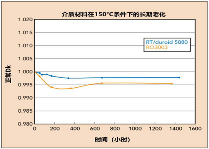
For nearly pure PTFE circuit materials, such as Rogers' RT/duroid 5880 boards, the electrical performance is very stable over long periods of use and at high temperatures (above room temperature or 25°C). For materials where PTFE is combined with other materials to adjust the dielectric constant (Dk) or to provide the required performance for a particular circuit (e.g., millimeter-wave bands), the performance varies over time and temperature depending on the other materials. For example, Rogers' RO3003 material is a circuit material based on a PTFE resin system with ceramic fillers and other additives used in automotive radar and millimeter-wave band circuit applications. As shown in Figure 1, it exhibits different aging characteristics than materials based on almost pure PTFE.

Figure 1: Long-term aging of RT/duroid 5880 board and RO3003 board dielectrics
As shown in Fig. 1, the thermal aging characteristics of both materials show relatively small changes: the change in Dk or relative dielectric constant (ε r) is less than 1%. Initially both materials show a decrease in Dk, which is related to the drying out of the material at 150°C. The material is also characterized by a decrease in Dk, which is related to the drying out of the material at 150°C. Although both materials are low hygroscopic, at the microscopic level they carry some moisture prior to testing. When moisture is removed from the material at high temperatures, Dk decreases. The PTFE formulation of RO3003 circuit boards is more complex than that of RT/duroid 5880 materials and reacts differently to high temperatures and drying. However, for long-term aging at 150°C, a Dk change of less than 1% is considered very robust for both materials.
Compared to thermoplastic materials, thermosets show a somewhat larger change in Dk for long term exposure to high temperatures. However, the amount of Dk change is closely related to the formulation of the thermoset material, and the reasons for the Dk change in thermosets are quite different from those in thermoplastics.
The natural reaction of thermoset circuit materials under high temperature conditions is oxidation. Oxidation is slow at room temperature, but accelerates at higher temperatures. Oxidation of thermoset substrates is limited to the depth of oxidative penetration into the material, and the reaction at the surface of the material changes as more oxide builds up on the surface until the oxidation process stops. For thermoset materials, the rate of oxidation and the depth of oxide penetration into the material will depend on the formulation of the material. For example, there are many types of antioxidants (AOs) that can be included in a formulation to slow down the oxidation process, and depending on the material formulation, some antioxidants are more effective than others.
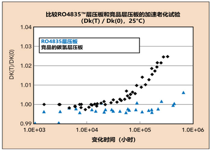
Figure 2 compares two thermoset hydrocarbon circuit boards, one with poorer oxidation properties and the other containing the most antioxidant AO components to minimize oxidation effects and provide robust long-term aging performance. The benefit of adding AO can be seen in the stability of Dk over time. The data in Figure 2 shows the change in Dk over time under high temperature conditions as measured by the X-band stationary ribbon resonator test method. The test material was fully exposed to the environment, and the data shown are extrapolated to longer times using the Arrhenius equation.This accelerated aging method allows for the extrapolation of long-term thermal aging effects without the need for long testing times. The test data compares a hydrocarbon circuit board to Rogers' RO4835 circuit material,which has a long history of stable aging resistance. The RO4835 material inherits the characteristics of the RO4350B circuit board and has identical electrical performance. As a reference to the time scale in Fig. 2, 1.0E+05 hours is equivalent to 11.4 years.

Figure 2: Comparison of the long-term aging of thermoset hydrocarbon circuit materials at 25℃
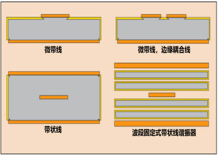
The Dk test of the aging test is based on the X-band fixed ribbon resonator test method defined in IPC-TM-650 2.5.5.5c to evaluate the Dk variation of the material.The test frequency is 10 GHz and the samples are completely etched out of the copper foil, leaving only the dielectric material. When evaluating the ageing of the circuit material in circuit form,the ageing effect is different because the copper layer protects the dielectric material from oxidation. The amount of protection depends on the different structures shown in Figure 3.

▲Fig. 3: Simple side view showing the different RF structures and how the oxidation (yellow color) penetrates the thermosetting dielectric material.
The depiction in Fig. 3 gives an approximation of how oxidation can form on dielectric materials.Oxidation forms on the bare substrate surface, and some of it even reaches the underside of the copper-clad conductor. In other words, most of the oxidation is on the surface of the material, and as the gradient of oxidation accumulates,a small amount of oxidation goes below the surface, but this below-surface oxidation is gradually reduced.
The Dk and Df of the circuit material will become larger in the presence of oxidation.Several factors will determine the extent to which oxidation affects the RF/microwave/millimeter wave electrical performance of the circuit material. The thinner the dielectric circuit the more it will be affected because the oxidation will be a greater percentage of the overall dielectric material.
Depending on the electromagnetic (EM) field in the circuit, the effect of oxidation will be different for different structures of RF/microwave/millimeter wave circuits. For example, for a microstrip line, where most of the EM field is located between the bottom of the signaling conductor and the top of the ground layer,and where there are strong edge fields to the left and right of the signaling conductor, the signal will change due to sufficient oxidation.Although the microstrip line may not be significantly affected by oxidation,the effects of oxidation can be detected at high millimeter wave frequencies.This effect is less for thicker microstrip line circuits than for thinner microstrip line circuits.
As is evident from the position of the signal conductors, the strip line structure is generally unaffected by oxidation (Fig. 3). However, for microstrip line edge-coupled circuits, where the coupling field is located on the surface of the pcb and approximately below and intersects the oxide layer, oxidation reduces RF/microwave/millimeter-wave performance. The effect of oxidation on grounded coplanar waveguide (GCPW) circuits on thin substrates may also be significant at millimeter-wave frequencies.
Dielectric Characterization Demystified
In the material aging process and testing performed, the dielectric material characteristics are determined by the X-band fixed ribbon resonator test method. Since the dielectric material is completely exposed to the environment during aging, all surfaces of the dielectric material are oxidized as shown in Figure 3. In other words, all eight surfaces of the dielectric are oxidized when the material is placed in a stationary ribbon resonator to form a ribbon resonator. Depending on the material to be tested, the amount of material to be placed in the fixture varies, and the oxidation also varies. However, the oxidation of the material is much greater in this measurement method than in the circuit-based test.
To prevent the effects of oxidation, the RO4835 circuit board is formulated with an optimum combination of AO additives. In addition to this, the RO4835 circuit board utilizes the same formulation as the conventional RO4350B circuit material, which has been a reliable circuit material substrate for high power RF/microwave circuits. Due to the optimal combination of AO additives, RO4835 boards require 10 times longer than RO4350B boards to achieve the same level of oxidation.
In fact, in addition to the oxidation difference, RO4350B boards exhibit good long-term aging performance in high-power applications. Generally, long-term aging problems with RO4350B boards are associated with circuits that have coupling characteristics, such as directional couplers. In order to better understand the role of circuit characteristics in the long-term aging performance of circuit materials, a comparison was made between a material with circuit characteristics and the same dielectric material treated with the same piping but without copper (where the copper is completely corroded away and has no circuit characteristics).
A variety of circuit configurations from Rogers' RO4350B circuit boards and RO4350B LoPro circuit boards were used for this comparison. The circuits included 50Ω microstrip line circuits, microstrip line edge-coupled bandpass filters, and microstrip line step impedance low-pass filters. The RO4350B LoPro boards are identical to the company's RO4350B boards, except they utilize a smoother, low-profile copper foil to reduce insertion loss at RF/microwave/millimeter wave frequencies.

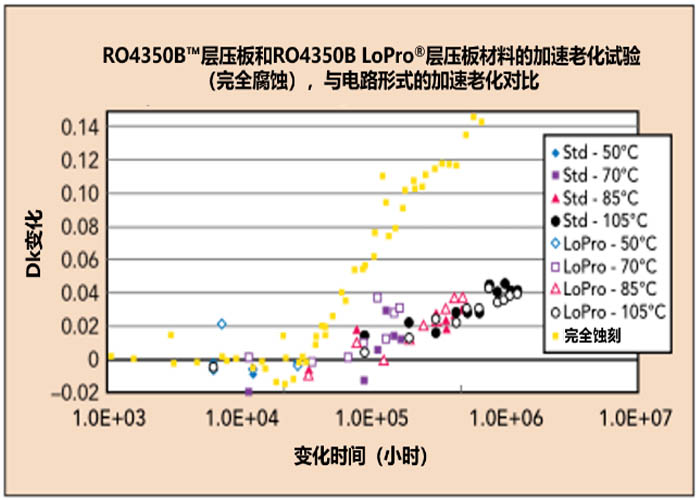
Figure 4: Comparison of bare dielectric material (fully corroded) with 50Ω microstrip circuitry on 20-mil RO4350B circuit board (Std) and 20-mil RO4350B LoPro circuit board (LoPro).
Figure 4 compares multiple long-term aging effects for two circuit materials, RO4350B vs RO4350B LoPro. The largest change in Dk over time is in the material sample that is completely etched off the copper foil (labeled as fully etched), i.e., the bare dielectric material. The bare material, which had no circuitry on it, was characterized in a fixed X-band ribbon resonator fixture at +50°C. The X-band resonator was tested with a 50 Ω microstrip line, and the X-band resonator was tested with a 50 Ω microstrip line. For the circuit tested with a 50Ω microstrip line, the variation in Dk exhibited by the circuit at different temperature conditions was much smaller.
The samples evaluated for long-term aging using the transmission line circuit at high temperatures were found to require a much longer period of time (10 to 100 times) to achieve the same level of oxidation as the samples with the copper foil completely etched off. Figure 4 also shows the oxidation and Dk change for samples at various temperatures. If the test circuits are made of the same material but with different thicknesses, then the oxidation effects may be different.
The aging effects were studied using a low-pass step impedance filter similar to that used for the transmission line circuit samples. Microstrip line edge-coupled bandpass filter samples are affected by oxidation to a greater extent. It still takes 3 to 5 times longer to achieve the same level of oxidation as a (bare dielectric) sample with the copper foil completely etched off. Tightly coupled circuits are more affected by oxidation than loosely coupled circuits. In addition, the oxidation time span varies depending on the test temperature, and the difference in Dk of the circuit material due to oxidation is greatest under the highest temperature conditions.
Soldermask,Parylene coating, and moisture-proof insulation can reduce the effects of thermoset oxidation when applied to circuits.Soldermask significantly reduces the effects of aging,but usually also reduces RF performance.Parylene coatings also help to minimize the oxidation effects of long-term aging when applied at thicknesses of 25 μm or more.HumiSeal also helps to minimize the effects of oxidation, and although there are many types available,some are more effective in reducing the effects of aging.
Circuit materials are exposed to high temperatures for short periods of time during processing and for long periods of time during use. The effect of prolonged high temperatures is often thought to be the accumulation of oxidation on the thermoset dielectric material of the circuit board,which can lead to a shift in the Dk of the circuit material. Determining the sensitivity of a circuit material to the effects of long-term aging requires precise and careful testing,as different measurement methods and technologies yield very different measurement results when characterizing high-frequency circuit materials. Choosing the right test method, whether it is material-based or circuit-based,will provide reliable data when modeling Dk and circuits.