Filter is one of the key devices in RF system, which is mainly used for frequency picking, so that the demanded frequency signal can pass through and reflect the unwanted interfering frequency signal. A practical example of a classic filter application is the front end of a transceiver or transmitter, as shown in Figures 1 and 2:
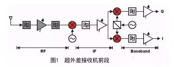
Filter Applications
As can be seen from Fig. 1, filters are widely used in RF, IF and baseband localization in transceivers. Of course, with the advancement of digital technology, the use of digital filters has been considered appropriate to replace the simulation filters in the baseband area and even in the IF area, but the filters in the RF area can not be replaced. Because of this, the filter is one of the key devices necessary in the RF system.
There are many ways to categorize filters. For example:
According to the special nature of frequency selection, they can be categorized as: low pass, high pass, band pass, band reject filters, etc;
According to the form of successful realization, they can be divided into: LC filters, acoustic and external waves/audible vibration wave filters, helical filters, media filters, cavity filters, high temperature superconducting filters, and the simplest surface structure filters.
According to different frequency response functions, we can categorize them into Chebyshev, generalized Chebyshev, Butterworth, Gaussian, Bethel function, and duck-egg-circle function, and so on.
The classification of different filters is mainly based on the special characteristics of different filters to describe the different characteristics of filters.
The different characteristics of filters depicted in this classification of filters focus on the need for comprehensive consideration of the actual engineering applications of filters, that is to say, the user needs to do the preset, the need for comprehensive consideration of the problem of user needs.
When selecting filters, the first thing that needs to be recognized is that low-pass, high-pass, band-pass or band-reject filters should be used.
In the following, we will first introduce the special characteristics of the frequency response and their effectiveness, which are categorized by the special characteristics of frequency selection, such as high-pass, low-pass, band-pass, and band-resistive
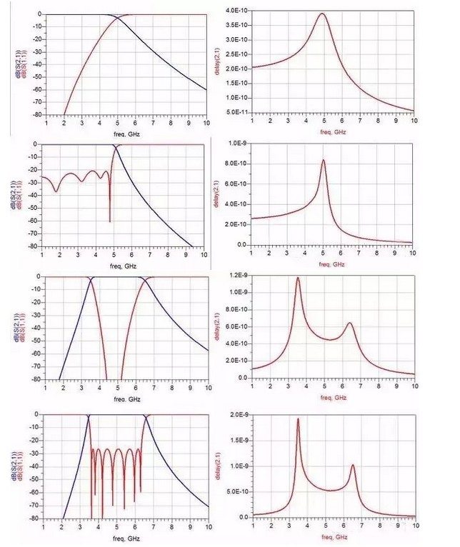
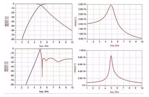
Butterworth Chebyshev Band Pass Filter
The most commonly used filters are low pass and band pass.The low pass is widely used in mixer localized mirroring, frequency source localized harmonic constraints, etc. The band pass is widely used in transceiver front-end signal picking, transmitter post-amplifier spurious constraints, and frequency source spurious constraints. Bandpass is widely used in signal selection at the front-end of transceivers, noise suppression after transmitter amplifiers, and noise suppression at frequency sources.
Filters are widely used in microwave RF systems, and as a functional device,there must be a corresponding electrical performance index to characterize the performance needs of the system for the device.
For different applications,there are different requirements for certain special characteristics of the filter's electrical performance.
Describe the filter electrical performance specifications are:
Class (Level)
Full bandwidth/relative bandwidth
Cutoff Frequency
Standing Wave
Out-of-Band Constraints
Ripple
Wear and tear
Passband bumplessness
Phase Linearity
Full group delay
Group delay teasing
Power Capacity
Phase uniformity
Amplitude uniformity
Office Temperature Range
The following is a step-by-step explanation of these electrical performance indicators of filters.
Order (steps): For high-pass and low-pass filters, the order is the total number of capacitors and inductors contacted by the filter.For bandpass filters,the steps are the total number of parallel harmonizers; for band reject filters,the steps are the total number of series and parallel harmonizers.
Full Bandwidth/Relative Bandwidth:This is the bandwidth used in bandpass filters to characterize the frequency range of the signal that can pass through the filter, which shows the frequency selection of the filter. Relative bandwidth is the percentage of the full bandwidth to the core frequency.
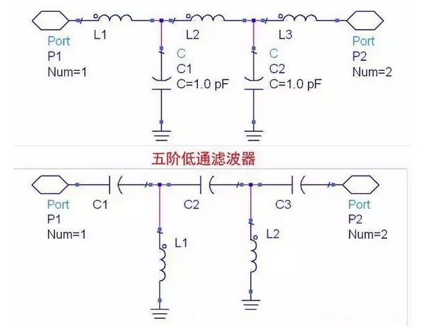
5-Stage High Pass Filter
Cutoff Frequency: The cutoff frequency is generally used in high pass and low pass filters. For low-pass filters, the up to frequency represents the range of frequencies that the filter can pass through; for high-pass filters, the up to frequency represents the range of frequencies that the filter can pass through at the lowest level.
Standing wave: The S11 measured by the vector network, which indicates how well the impedance of the filter port matches the required impedance of the system. It indicates how much of the input signal fails to enter the filter and is reflected back to the input.
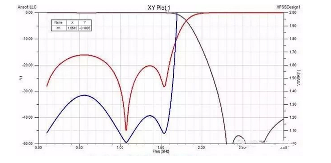
Ninth order low pass filter simulation curve
Casualty: Casualty expresses the loss of energy at black ram after the signal passes through the filter, i.e., the energy at black ram consumed by the filter.
Passband bumplessness: The exact value of the difference between the maximum and minimum values of the passband of the filter. The difference between the maximum value and the minimum value of the blackout loss in the passband of the filter is the difference between the blackout loss and the maximum value of the blackout loss at different frequencies.
Out-of-band constraint: The “attenuation” outside the passband frequency range of the filter. It is an indication of the filter's experience in selecting signals of different frequencies.
Ripple: The difference between the peaks and troughs of the S21 curve in the passband of the filter.
Phase Linearity: The phase difference between the phase of the filter passband frequency range and a channel transmission line with a time delay equal to the core frequency. It characterizes the particular nature of the filter's dispersed color light.
Full Group Delay: The time it takes for a signal in the passband of a filter to travel from the input channel to the output channel.
Group Delay Tease: The difference between the maximum and minimum values of the full group delay within the passband of the filter. It characterizes the special nature of the dispersed color light of the filter.
Power Capacity: The maximum power that can be input into the passband signal of the filter.
Phase Identity: The difference in the phase of the signals transmitted between different batches of filters of the same rating.It symbolizes the difference between batches of filters.
Amplitude Identity: The difference in signal loss between different filters in the same batch with the same quota.It characterizes the difference between batches of filters (identical).
Phase Linearity: The difference in phase between a filter's passband frequency range and a channelized transmission line with a time delay equal to the core frequency.Characterizes the particular nature of the filter's dispersed color light.
Full Group Delay: The time it takes for a signal in the passband of a filter to travel from the input channel to the output channel.
Group Delay Tease: The difference between the maximum and minimum values of the full group delay within the passband of the filter. It characterizes the special nature of the dispersed color light of the filter.
Power Capacity: The maximum power that can be input into the passband signal of the filter.
Phase Identity: The difference in the phase of the signals transmitted between different batches of filters of the same rating. It symbolizes the difference between batches of filters.
Amplitude Identity: The difference in signal loss between different filters in the same batch with the same quota. This characterizes the difference between batches of filters.
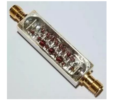
LC Filter
Outside and outside acoustic wave/audible vibration wave filters
The acoustic meter is a filter that successfully realizes the resonance effect of the audible vibration wave by converting the electrical energy into the form of audible vibration wave on the exterior. The uniqueness of this EAW filter is that it is very small in size,has a relatively high Q value, and is suitable for mass production using the transistorization process.The size of an 800MHz or so filter is approximately the volume of a 0805 capacitor. The lack of power capacity is small, not comfortable for small batch customized products,long development cycle and high development cost.
Acoustic filters are generally used in consumer electronics products.
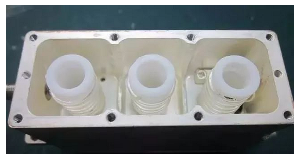
Spiral Filter
Spiral Filter: Spiral filter is a kind of semi-integrated parametric filter, which is considered suitable and uses the self-resonance of the spiral inductor placed in the cavity to successfully realize the resonator, and the spatial magnetic field through the neighboring resonator to successfully realize the coupling.
The advantages are: the size is smaller than the cavity, and the Q value and power capacity are higher than that of LC. The disadvantages are: it is more difficult to successfully realize the broadband, high frequency local inductance is not easy to successfully realize.
Spiral filters are generally used in the following 500MHz 20% relative bandwidth, 100W uniform power, the insertion loss of the necessary requirements of the occasion.
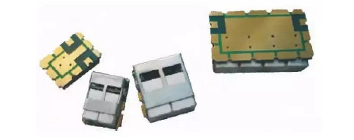
media filter
Ripple Filter: The difference between the peaks and valleys of the S21 curve rise and fall in the filter passband.
Media Filter: A media filter is a half-aggregate filter that successfully realizes a quarter-wave reference line or a half-open line supplemented by a medium as deemed appropriate. The advantage is that the Q value is higher than that of LC, and it can successfully realize a filter with higher frequency than LC filter. The disadvantage is that the parasitics are closer and the resonator needs to be customized.
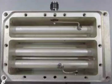
Comb Cavity Filter
The most unique feature of crossfinger filters is that they can successfully realize wide bandwidth,which is generally up to 60% wider than the relative bandwidth if a redundant resonator rod is used as appropriate, taking into account the linearity of the machine.At the same time,in the K-band,the wideband comb filtering processor is basically impossible to process and the adjustment screws cannot be placed,because of which the cross-finger structure is generally considered to be suitable under these conditions.The parasitic passband of the cross-finger structure is closer to that of the comb structure,and generally the parasitic passband is around 1.8F0.Under the same size, the cross-finger filter has a larger power capacity than the comb filter.
Filter is a key device necessary for wireless communication system.
There are many types of filters, and various filters have different performance unique place,because of this in the filter selection,generally need to comprehensively consider the problem of customer's actual use of the background and customer performance needs to be able to make accurate,useful and reliable selection.
When the concept of filter quota is relatively rare, it is generally necessary to ask the customer about the size,wear and tear, the frequency of out-of-band control,the degree of control,and the power capacity. Based on these few simple requirements, we can basically determine the type of filter.