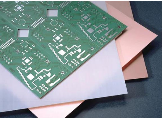
As more and more millimetre wave circuits are using multi-layer PCBs, their need for circuit board materials is increasing. These materials must not only meet the electrical performance requirements of high frequency/high speed circuits, but also the mechanical requirements of multilayer circuits. These multi-layer PCBs usually consist of a circuit laminate and a bonding sheet (adhesive material) to be laminated together. For higher frequency applications, such as millimetre wave frequencies, Rogers' RO3003™ circuit board material achieves low loss circuit characteristics. This PTFE circuit laminate based on a low Dk ceramic filler has a z-axis (thickness direction) Dk of 3.00 at 10 GHz and a Df of 0.0010 at 10 GHz; thicknesses ranging from 0.005 inches (0.13 mm) to 0.060 inches (1.52 mm) are available.

RO3003™ material has been widely used in 77 GHz single-layer circuit boards with reliable dimensional stability and temperature behaviour. It also performs reliably on multi-layer PCB structures. The material has the same coefficient of thermal expansion (CTE) as copper in the x and y axes, approximately 17 ppm/°C, for high dimensional stability in multilayer PCB assemblies. z-axis CTE of 25 ppm/°C enables stable and reliable plated-through-hole (PTH) plating when microvias need to be designed between the layers of the characteristic. In addition, it has low moisture absorption of 0.04%, making it suitable for different humid working environments.
The smoothness of the circuit laminate copper foil surface is especially important at higher frequencies, so Rogers designed and developed RO3003G2™ circuit board material. It is based on the original RO3003™ laminate with optimised fillers to reduce the porosity of the dielectric and the surface roughness of the copper foil. The dielectric Dk and Df values of RO3003G2 and RO3003 are nearly identical, but RO3003G2 uses a smoother copper foil, resulting in less loss at millimetre wave frequencies. At the same time, RO3003G2 inherits the good coefficient of thermal expansion (CTE) performance of RO3003 laminates in the xy-plane, with an optimised packaging system that brings the Z-axis CTE value (18 ppm/°C) closer to that of Cu, and a very reliable metallised through-hole (PTH) performance. (PTH) performance. Material thicknesses of 0.005 in (0.13 mm) and 0.010 in (0.25 mm) are available.
CLTE-MW™ circuit board materials meet the performance requirements of circuits when mechanical stability and thinner board materials are a consideration, such as in multi-layer PCBs where size and weight must be minimised. CLTE-MW™ materials feature an open glass fibre structure and a low Dk ceramic filler system for excellent dimensional stability. Available in thicknesses ranging from 0.003" (0.076 mm) to 0.010" (0.25 mm), CLTE-MW™ materials meet ground spacing requirements for different signals while minimising the size and weight of multi-layer circuit board components. CLTE-MW™ materials have Z-axis Dk values of 2.94 to 3.02 over 10 GHz for various thicknesses, good CTE performance and PTH reliability, and very low moisture absorption of 0.03% for a wide range of challenging operating environments.
The role of bonding materials and semi-cured sheets is not only to hold the layers of a multi-layer PCB circuit together, they also become part of the PCB. Therefore, they need to be selected based on their electrical, mechanical and adhesive properties. Take Rogers' 2929 bonding material as an example. It is compatible with both flat-pressure and high-pressure bonding methods when processing multi-layer PCBs. The 2929 bonding material is also available in different thicknesses. It has a Dk value of 2.94 on the Z-axis at 10 GHz, and it has a low Df value of 0.003. The low Z-axis expansion coefficient guarantees reliable plated through-holes and compatibility with PTFE-containing circuit board materials. Strong bonding of PCBs.
Rogers' SpeedWave™ 300P is a prepreg, fully RoHS compliant, semi-cured sheet material that can be assembled lead-free throughout. It can be used to process FR-4 and PTFE-containing circuit board materials such as CLTE-MW laminates. The prepreg has a low Dk of 3.0 to 3.3 (depending on the thickness) and a low Df value of 0.0019 to 0.0022, good flow and filling characteristics, and a low Z-axis expansion for reliable plated through-holes. Especially in advanced digital circuits, a wide range of fibre-openings and standard glass cloth configurations are available, as well as combinations of different resin contents for optimum bonding.
With the increasing popularity of millimetre wave bandwidth, multilayer PCB containing millimetre wave circuits will also become more common, with more layers and smaller sizes. By choosing the right board material and prepreg, everything will be bonded together more tightly.
iPCB® is a professional manufacturer of high precision pcb boards, we can mass produce 4-46 layers pcb boards, circuit boards, circuit boards, high frequency boards, high speed boards, HDI boards, pcb circuit boards, high frequency and high speed boards, IC packaging boards, semiconductor test boards, multilayer circuit boards, hdi PCB boards, mixed voltage boards, high frequency boards, rigid/flexible boards, and so on.