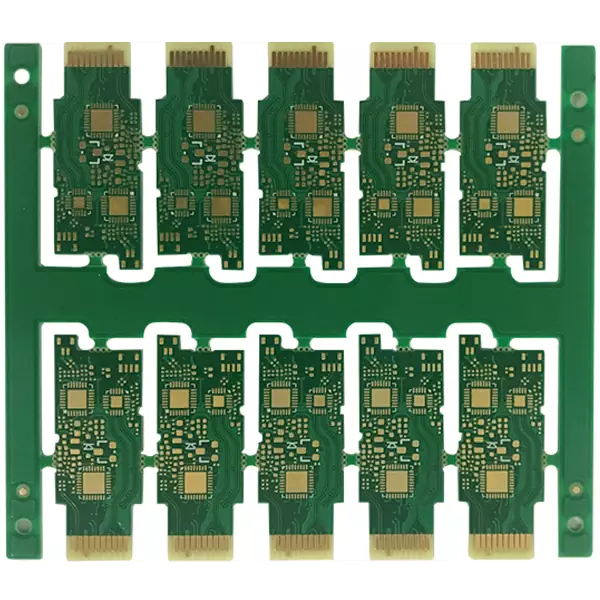
Product Name: Optical module PCB
Substrate: M6
Layer: 6L
Thickness: 1.0mm
Copper plating thickness: 1/H/H/1oz
Surface treatment: immersion gold
Golden Finger: 5u" Gold + 45 degree oblique edge
Minimum line width/spacing: 4/4 mil (100/100 μ m)
Technical requirement: Strict external tolerance
Product applications: Optical module
Optical module consists of optoelectronic devices, functional circuits, and optical interfaces. Optoelectronic devices include two parts: emitting and receiving. The function of an optical module is to convert electrical signals into optical signals at the transmitting end, transmit them through optical fibers, and then convert the optical signals into electrical signals at the receiving end.
An optical module is an optoelectronic device that performs photoelectric and electro-optical conversion. The sending end of the optical module converts electrical signals into optical signals, while the receiving end converts optical signals into electrical signals. Optical modules are classified according to their packaging forms, commonly including SFP, SFP+, SFF, Gigabit Ethernet Interface Converter (GBIC), etc.
Optical modules can be divided into optical receiving modules, optical transmitting modules, optical transceiver integrated modules, and optical forwarding modules. The main function of the integrated optical transceiver module is to achieve optoelectronic/electro-optical conversion, including optical power control, modulation transmission, signal detection, and limiting amplification decision regeneration functions. Common ones include SFP, SFP+, GBIC, XFP, 1x9, etc.
The current application scenarios of optical modules can be mainly divided into two major fields: data communication and telecommunications networks. The data communication field mainly refers to the Internet data center and enterprise data center. Telecommunications networks mainly include fiber optic access networks, metropolitan area networks/backbone networks, and mobile network applications represented by 5G access and bearer networks.
The data communication scenario mainly includes a large number of network switches and server clusters placed in the host room of the enterprise data center and the Internet data center. They are the core of the generic cabling and information network equipment, and also the data aggregation center of the information network system. The connection between servers, switches, and between servers and switches requires the use of transmission carriers such as optical modules and optical fibers to achieve data interoperability.
The telecommunications scenario mainly includes the mobile access network side, and the interconnection of RRU and BBU devices relies on optical modules and fiber jumpers. The metropolitan access layer, aggregation layer, core layer/provincial trunk line that carry the network mainly rely on optical modules to achieve interconnection between devices in each layer, in order to realize the forward and backward transmission functions of 5G services.

Optical modules
The main components of the optical module include:
1. CDR (Clock and Data Recovery): The function of a clock and data recovery chip is to extract the clock signal from the input signal and find the phase relationship between the clock signal and the data, which is simply called clock recovery. Meanwhile, CDR can also compensate for the loss of signals on the wiring and connectors.
2. LDD (LaserDiode Driver): Convert the output signal of CDR into the corresponding modulation signal to drive the laser to emit light. Different types of lasers require the selection of different types of LDD chips. In short-range multi-mode optical modules (such as 100G SR4), CDR and LDD are generally integrated on the same chip.
3. TOSA: Implementing electrical/optical conversion, mainly including devices such as lasers, MPDs, TECs, isolators, Mux, coupling lenses, etc., available in TO-CAN, Gold BOX, COC (chip on chip), COB (chip on board) and other packaging forms. For optical modules applied in data centers, TEC, MPD, and isolators are not essential to save costs. Mux is only available in optical modules that require wavelength division multiplexing. In addition, some optical modules' LDDs are also encapsulated in TOSA.
4. ROSA: Implementing optical/electrical conversion, mainly including PD/APD, DeMux, coupling components, etc., with packaging types generally the same as TOSA. PD is used for short and medium range optical modules, while APD is mainly used for long-distance optical modules.
5. TIA (Transimpedance Amplifier): Used in conjunction with detectors. The detector converts the light signal into a current signal, and TIA processes the current signal into a voltage signal of a certain amplitude. We can simply understand it as a large resistor.
6. LA (Limiting Amplifier): The output amplitude of TIA will change with the variation of received optical power. The role of LA is to process the changing output amplitude into an equal amplitude electrical signal, providing stable voltage signals to CDR and decision circuits. In high-speed modules, LA is usually integrated with TIA or CDR.
7. MCU: Responsible for running underlying software, monitoring DDM functions related to optical modules, and performing specific functions. DDM monitoring mainly realizes real-time monitoring of five analog signals, including temperature, VCC voltage, Bias current, Rx power, and Tx power, to determine the working condition of the optical module and facilitate the maintenance of the optical communication link.
Optical module, as the core device for achieving optoelectronic conversion in optical communication, is widely used in data centers. Traditional data centers mainly use 1G/10G low-speed optical modules, while cloud data centers mainly use 40G/100G high-speed modules. With the rapid growth of global network traffic driven by new application scenarios such as high-definition video, live streaming, and VR, emerging application demands such as cloud computing, IaaS services, and big data are placing higher demands on data transmission within data centers to meet future development trends. This will drive the emergence of optical module with higher propagation rates in the future.
Product Name: Optical module PCB
Substrate: M6
Layer: 6L
Thickness: 1.0mm
Copper plating thickness: 1/H/H/1oz
Surface treatment: immersion gold
Golden Finger: 5u" Gold + 45 degree oblique edge
Minimum line width/spacing: 4/4 mil (100/100 μ m)
Technical requirement: Strict external tolerance
Product applications: Optical module
iPCB Circuit provides support for PCB design, PCB technology, and PCBA assembly. You can request technical consultation or quotation for PCB and PCBA here, please contact email: sales@ipcb.com
We will respond very quickly.