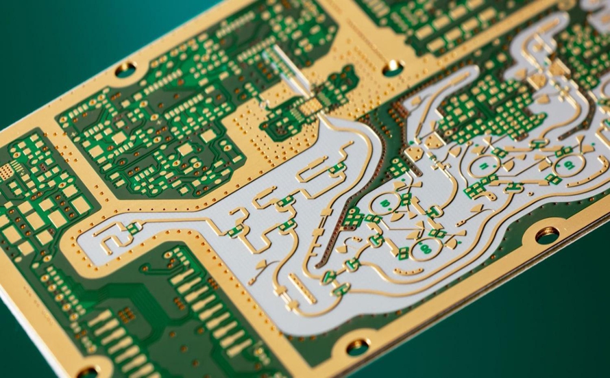
Weather radar systems are the cornerstone of modern meteorology, providing real-time monitoring and forecasting of severe weather such as typhoons, thunderstorms, and hail. Their ability to detect precipitation intensity and velocity depends heavily on high-frequency radio signals. Printed Circuit Boards (PCBs), as the physical foundation for radar transmitters, receivers, and signal processors, play a critical role in ensuring system reliability and accuracy. Unlike conventional consumer electronics, radar PCBs must withstand extreme frequencies, power levels, and environmental conditions.
1.Technical Requirements of Weather Radar PCBs
Weather radar systems typically operate in S-band (2–4 GHz), C-band (4–8 GHz), and X-band (8–12 GHz). Each band places unique demands on PCB materials and design.
* Frequency range: A typical C-band weather radar operates around 5.6 GHz.
* Power handling: Transmitters often exceed 250 kW peak power, requiring PCBs capable of handling high voltages and current surges without breakdown.
* Environmental durability: Outdoor radars are exposed to wide temperature ranges (–40°C to +85°C) and humidity levels up to 95%RH, demanding boards with strong moisture and corrosion resistance.
Meeting these requirements involves precise material selection, impedance control, and advanced protection methods.
2.Material Selection and Performance
The choice of substrate material directly affects signal integrity at high frequencies.
| FR-4 | 4.3–4.6 | 0.020–0.025 | Low cost, high loss above 3 GHz
| Rogers RO4003C | 3.38 | 0.0027 | Low-loss, widely used in C/X band radars
| PTFE (e.g., RT/duroid 5880) | 2.2 | 0.0009 | Extremely low loss, suitable above 8 GHz, harder to process
For instance, in one C-band radar receiver front-end, Rogers 4350B was used to fabricate microstrip lines. At 5.6 GHz, the insertion loss was measured at 0.12–0.15 dB/inch, compared with over 0.8 dB/inch for FR-4. This reduction in transmission loss significantly improved signal-to-noise ratio and overall radar sensitivity.

3.Key Design Challenges
(1). Signal Integrity and Impedance Control
Radar RF circuits demand 50Ω controlled impedance with tolerances within ±5%. Even small deviations can lead to mismatched reflections and degraded detection accuracy. Simulation tools such as HFSS and ADS are often used during design to model microstrip and stripline geometries.
(2). Power Handling
High transmit power requires wide traces or heavy copper foils. For example, copper thickness of 2 oz (70 µm) or more is commonly adopted to carry currents exceeding 10 A. Thermal vias are added under power devices to dissipate heat efficiently.
(3). Environmental Reliability
Field-deployed radars face rain, salt fog, and UV radiation. To mitigate this, PCBs are often finished with ENIG (Electroless Nickel Immersion Gold) for corrosion resistance, and coated with conformal coatings to prevent moisture ingress.
(4). High-Density Layout and Thermal Management
The radar back-end includes high-speed ADCs and FPGAs for signal processing, requiring dense interconnections and controlled impedance traces. Designers often use HDI PCBs with stacked microvias and embedded thermal vias to improve routing density and heat dissipation.
4.Case Study with Performance Data
A C-band dual-polarization weather radar deployed in Asia adopted Rogers 4350B for its receiver boards:
* Board thickness: 0.8 mm
* Copper thickness: 35 µm
* Controlled impedance: 50Ω, tolerance ±3%
* Operating frequency: 5.6 GHz
Laboratory tests showed:
* Insertion loss: 0.12 dB/inch
* VSWR < 1.15
* Receiver sensitivity improved by 4.5 dB compared with FR-4 prototypes
* Detection of small hailstones (1–2 mm diameter) increased significantly due to enhanced signal-to-noise ratio
These results illustrate how material selection and precision PCB design directly translate into improved radar performance.
5.Conclusion and Future Outlook
The PCB is not just a mechanical support but a critical enabler of weather radar performance. From high-frequency transmission to power handling and environmental durability, PCB technology dictates the accuracy and reliability of meteorological observations.
Looking ahead, as radars move toward higher frequency bands such as Ku and Ka (12–35 GHz) for finer resolution, requirements for ultra-low-loss substrates and advanced PCB technologies will intensify. Likely trends include:
* Broader adoption of PTFE and ceramic-based substrates for minimal loss
* Use of thick copper boards for high-power applications
* Integration of advanced surface protection for extreme climates
* Growing importance of PCBA-level solutions, combining assembly and board manufacturing for higher reliability
Weather radar performance is only as strong as the PCBs that support it. With the continuous evolution of radar technology, advanced PCB design and materials will remain at the forefront of reliable meteorological monitoring.