When designing high speed PCB,we will understand the concept of impedance.So why do we need to control impedance when designing high-speed PCBs?Which signals need to control impedance and what impact does not controlling impedance matching have on our circuits?
What is impedance matching
Impedance matching is mainly used on transmission lines to achieve the purpose of all high frequency microwave signals being transmitted to the load point,and no signal is reflected back to the source point,so that the input section and output end of our transmission line are in an impedance matching state,referred to as impedance matching.
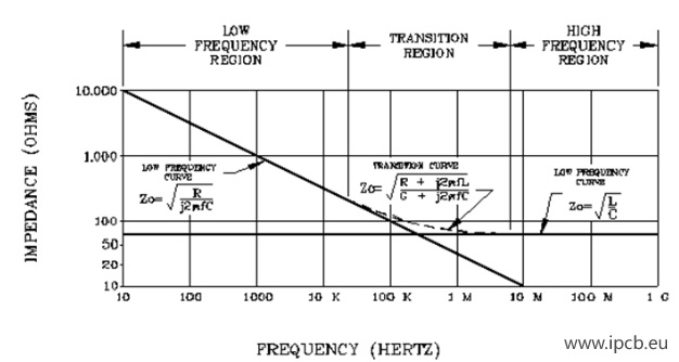
The continuity of characteristic impedance (ρ) basically depends on the stability of the ratio of distributed parameters L0 and C0. We all know Ohm's law: U=RI, where R is the resistance or resistive load, in ohms (Ω). Resistance is related to the resistivity (also known as conductivity) of metal materials, but in the process of high-frequency signal transmission, we also need to understand the transmission characteristics of the physical medium (such as twisted pair, coaxial cable, waveguide) that transmits high-frequency signals. It is different from low-frequency signals. This transmission characteristic is related to the conductive material (such as copper or silver) of the transmission medium, conductivity (resistivity), geometry (most commonly cylindrical), distributed inductance (L0), distributed capacitance (C0), dielectric constant of insulating materials, etc., while these distributed parameters and the dielectric constant of insulating materials are often not considered when transmitting low-frequency signals.
Impedance matching
Why do we need impedance matching?
Impedance matching can be omitted in low speed PCB design,but in high speed PCB design, in order to obtain complete,reliable,accurate,interference-free, and noise-free transmission signals, it is necessary to ensure that the circuit performance provided by the printed circuit board ensures that the signal does not reflect during transmission,the signal is complete,and the transmission loss is low, which plays the role of matching impedance. If the key signal does not achieve impedance matching, it may cause signal reflection, rebound, loss, etc., and the originally good signal waveform will be deformed,which will directly affect the performance and even function of our circuit.
What are the factors that affect impedance?
The factors that usually affect impedance are as follows
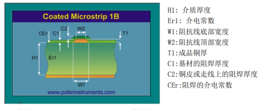
(1) Er--dielectric constant:
The dielectric constants of different boards are also different.
Common board materials at present include paper substrate (commonly known as cardboard, plastic board, V0 board, flame retardant board, etc.), epoxy fiberglass cloth substrate (commonly known as epoxy board, fiberglass board, fiberboard, FR4), composite substrate (commonly known as powder board, etc., cem-1 board is also called 22F in some places in China). At present, most board materials use FR-4. The Er characteristic of this material changes with the loading frequency. When the operating frequency is below 1GHZ, its Er is considered to be around 4.2. It will decrease slightly at the operating frequency of 1.5-2.0GHZ, so we need to pay attention to the operating frequency of the product in our actual application.
(2) H---Dielectric thickness:
This factor has the greatest impact on impedance control. For example, the accuracy of impedance is very high, so the design of this part should strive for accuracy. The composition of H of FR-4 is composed of various semi-cured sheets. Usually, our dielectric is divided into the dielectric thickness of the inner core board and the dielectric thickness of the laminated multilayer board.
(3) W---Trace width:
In our design, different line widths will also affect our impedance. Usually, we analyze and calculate the impedance according to the actual situation to get the appropriate line width.
(4) T---Trace thickness:
Usually, reducing the line thickness can increase the impedance, and increasing the line thickness can reduce the impedance.
Impedance Factors
4. What types of impedance lines are there?
Usually our impedance lines can be divided into single-ended impedance and differential impedance.In multi-layer boards, single-ended lines and differential lines refer to adjacent layers. It should be noted that in the processing of RF lines, interlayer reference will be made to ensure that the RF antenna achieves the best line width and thus the best performance. In addition, in order to achieve the effect of impedance matching when designing our two-layer boards, coplanar impedance is required.The so-called coplanar impedance means that the single-ended line or differential line that needs impedance matching usually refers to the copper foil on both sides of the signal line to achieve an impedance matching purpose.
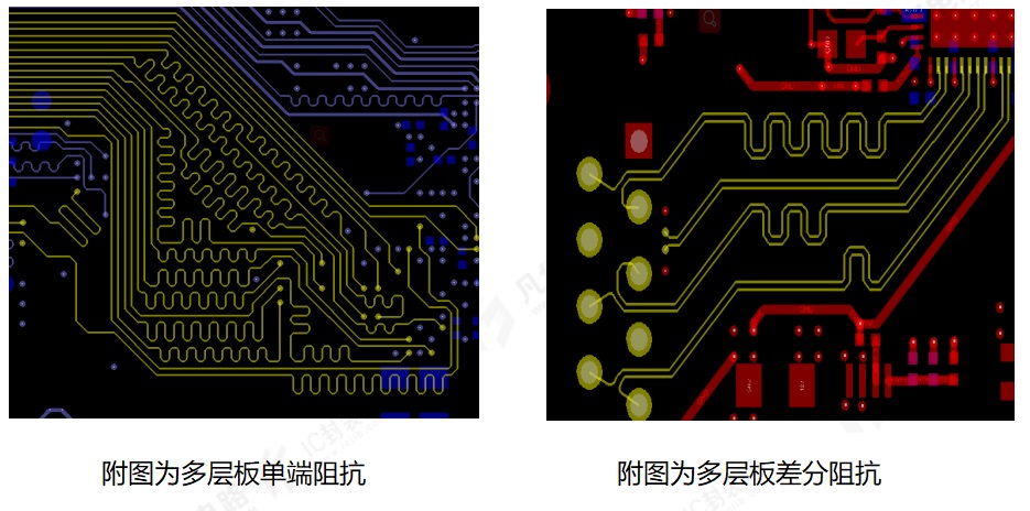
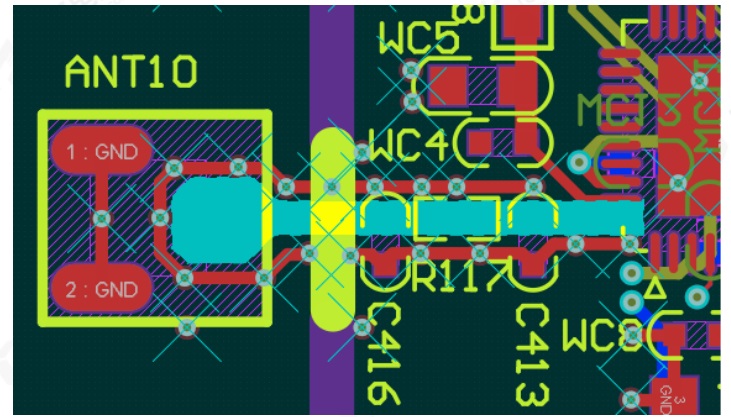
The attached figure shows the reference processing of the interlayer of RF single-ended impedance
(the figure is designed for a six-layer board, the antenna is placed on the top layer, and the GND plane of the second layer in the antenna area is hollowed out)
5. Which lines usually need impedance control, and how many ohms of impedance do you need to control?
Not all lines have impedance matching requirements. Only high-speed lines need impedance control. The impedance values of different signals are different. Differential impedances are 90om, 100om, 120om, etc. Generally, USB2.0 requires 90om impedance control, HDMI, USB3.0, MIPI, 100M network port, Gigabit network port, etc. are controlled by 100om impedance, and RS422 is generally controlled by 120om impedance. Single-ended lines generally control 50 om impedance?.
6. After completing the PCB design, how do you usually connect with the board factory to let them know which lines need impedance matching?
After we complete the PCB design, we usually explain the impedance matching of your board to our board factory in the form of screenshots. As shown in the figure below, mark the signal lines with different impedance values with colors, and then take a screenshot with text description!
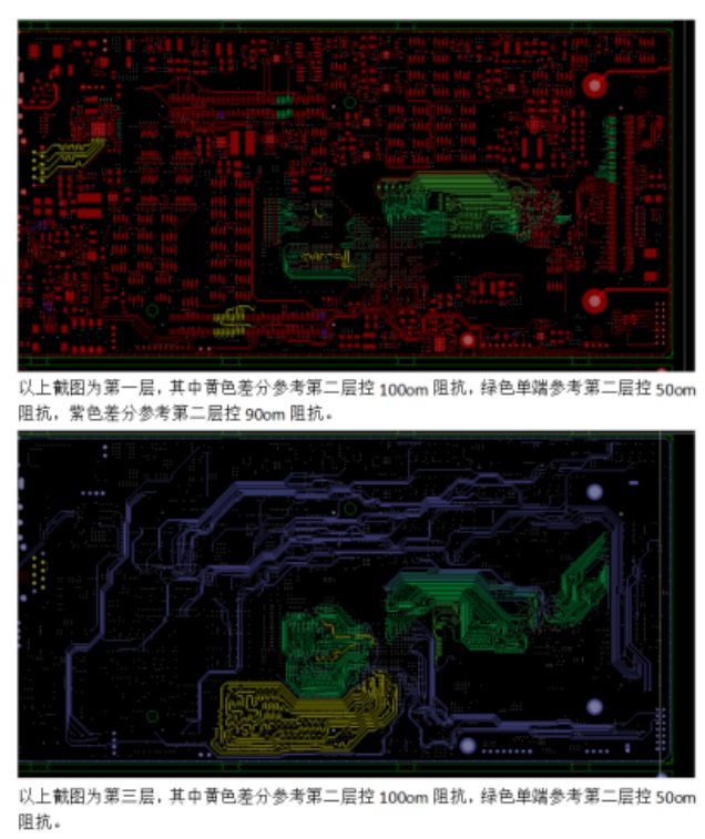
Impedance Matching
7. Why is the characteristic impedance of USB 90 ohms? USB devices are easy to use, support hot plugging, and have fast speeds. They are quickly widely used in information and communication products such as personal computers and mobile devices, and have been extended to other related fields such as photographic equipment, digital TVs (set-top boxes), and game consoles. It can be said that USB is currently the most successful I/O technology, and with the release of the current USB4 standard, the application scope of USB interfaces will inevitably be more extensive. Why is the characteristic impedance of USB 90 ohms, rather than 50 ohms, 75 ohms for coaxial cables, or 100 ohms for HDMI and Displayport?
When light transitions from air to water, reflection occurs due to differences in photoconductivity. Similarly, reflection happens in signal transmission when there's a mutation in characteristic impedance.At low frequencies, the wavelength is much longer than the transmission line, so reflection isn't an issue. However, at high frequencies, when the wavelength is similar to the line length, reflection can degrade signal quality. Impedance matching reduces reflection, ensuring signal integrity. For high-speed data transmission, like USB, matching a 90-ohm differential impedance is crucial. Without it, stability and speed suffer, leading to potential signal distortion and damage due to mismatched impedance.
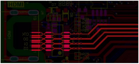
USB characteristic impedance
USB signals are typically differential signals,consisting of a positive and a negative trace with a 180-degree phase difference between them.This helps suppress common-mode interference and increases signal amplitude.There are two types of differential signals: tight coupling and loose coupling.In loose coupling,a ground plane between the traces can reduce crosstalk,while in tight coupling,the traces can be very close.Differential signals rely primarily on the ground plane for return paths.The 50-ohm coaxial impedance is commonly used in RF devices to ensure maximum signal power transmission,requiring connectors and PCB traces to match 50 ohms.However,USB defines a 90-ohm impedance based on experimental data,although 100-ohms could also be feasible.If the impedance is mismatched, such as with a 100-ohm trace, signal reflection and impedance matching issues will occur.