A Trustworthy PCB and Electronic Manufacturing Enterprise! Contact Us



Active high frequency componentsare the parts of a radio system that need DC power to amplify, mix, switch or generate signals. Every smartphone, radar module, satellite terminal and 5G base station relies on them, and the quality of these parts largely decides how far a signal travels, how clean it sounds and how much power the whole system burns. If you design, buy or build boards for RF equipment, it pays to understand what these devices do and what they expect from the circuit board underneath them.
This guide walks through the main device families, the semiconductor technologies behind them, the places they show up in real products, and the board-level details that engineers and buyers often overlook. It is written for people who work with these parts every day, and for people who have just been handed an RFQ with unfamiliar terms in it.
What Makes a Part “Active”
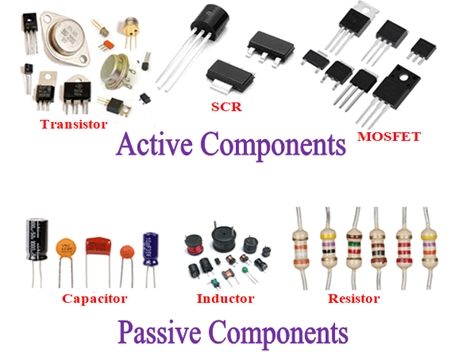
The easiest way to separate active parts from passive ones is to ask a simple question: does the device need a power supply to do its job?
A filter, a coupler, a power divider or a fixed attenuator works with nothing but the signal passing through it. It can shape, split or weaken that signal, but it cannot make it stronger and it cannot create a new frequency. These are passive parts.
An amplifier, a mixer, an oscillator or a switch with a control circuit behaves differently. It draws current from a supply, and it uses that energy to give the signal gain, to shift it to another frequency, to generate it from scratch or to steer it down a different path. That is the defining trait of active high frequency components, and it brings both power and trouble. Because they consume power, they produce heat. Because they use nonlinear semiconductor behavior, they create distortion and unwanted harmonics. Because they are sensitive to bias and layout, they can oscillate when a board is designed carelessly.
Some devices sit in a gray area. A digital step attenuator, for example, is mostly a network of resistors, but it contains FET switches and a control interface, so most engineers treat it as an active part. A digital phase shifter works the same way. In practice, if a device has a bias pin, a control bus or a supply pin, plan for it as active.
The Main Device Families
Low Noise Amplifiers
The low noise amplifier, or LNA, is the first active stage in a receiver. Its job is to lift a very weak signal above the noise of everything that follows, while adding as little noise of its own as possible.
The reason it sits first is explained by the Friis equation for cascaded noise. The noise figure of the first stage counts the most, and the noise of later stages is divided by the gain ahead of them. A good LNA at the front can make a mediocre mixer behind it look fine. A poor LNA ruins the sensitivity of the whole receiver no matter how good the rest is.
Designers look at a handful of numbers when they pick one. Noise figure comes first, and at lower microwave frequencies values below 1 dB are common, with the best parts reaching well under 0.5 dB. At millimeter wave frequencies the figure rises. An E-band LNA covering roughly 72 to 82 GHz might show a noise figure around 4 dB with about 30 dB of gain, which is a respectable result at that frequency. Gain, gain flatness, input and output return loss, output P1dB and third-order intercept point complete the picture. P1dB tells you where the amplifier starts to compress, and the intercept point tells you how badly it behaves when two strong signals arrive together.
Low noise devices are usually built on GaAs pHEMT, SiGe or, for the most demanding applications, InP HEMT processes. The input match is tuned for minimum noise, not maximum power transfer, which is why a good LNA datasheet always shows two separate curves.
Power Amplifiers
If the LNA is the careful listener, the power amplifier is the loud voice. It sits at the end of the transmit chain and pushes the signal up to the level the antenna needs.
Output power matters, but it is rarely the only concern. Efficiency decides how much of the supply power turns into heat, and in a compact module that heat is the main enemy. Linearity decides whether the transmitted signal stays inside its allotted channel. Modern waveforms such as OFDM have high peak-to-average ratios, so an amplifier that looks fine with a single tone can spread energy into neighboring channels when it carries real traffic. Engineers watch adjacent channel power ratio, error vector magnitude and third-order intermodulation for this reason.
GaN has become the default choice for high-power work in radar, electronic warfare and base stations because it handles much higher voltage and power density than GaAs. GaAs still dominates in phones and mid-power links, and silicon-based processes are growing fast in consumer millimeter wave arrays where cost and integration matter more than raw watts.
Every power amplifier is also a heat source, which makes it the part that most often drives decisions about the board material, copper weight and thermal path.
Mixers
A mixer moves a signal from one frequency to another. It has three ports: the RF port, the local oscillator (LO) port and the intermediate frequency (IF) port. Feed it an RF signal and an LO, and the nonlinearity of the diodes or transistors inside produces the sum and difference of the two frequencies. A filter then keeps the one you want.
Passive diode mixers are popular because they are quiet and linear, though they lose some signal as conversion loss and need a fairly strong LO drive. Active mixers based on the Gilbert cell topology can give conversion gain and need less LO power, but they usually trade away some linearity and use more current.
The numbers worth checking are conversion loss or gain, noise figure, port-to-port isolation (LO to RF leakage can be a real headache), compression point and image rejection. Image rejection matters because an unwanted signal on the opposite side of the LO can land on the same IF and cannot be filtered out afterward.
Oscillators, VCOs and Frequency Synthesis
Everything in a radio needs a reference, and oscillators provide it. A voltage-controlled oscillator, or VCO, changes its output frequency in response to a control voltage. On its own it drifts and wobbles, so it is normally wrapped in a phase-locked loop.
A phase-locked loop compares the VCO, after division, with a stable reference. Any difference produces an error signal. A loop filter smooths that error into a DC control voltage, and the voltage pulls the VCO back into line. When the loop settles, the divided output matches the reference exactly, so the output frequency equals the reference multiplied by the division ratio. A simple teaching circuit makes this clear. Take a 10 kHz reference, a VCO and two divide-by-ten counters in the feedback path. The loop will lock when the VCO runs at 1 MHz, because only then does the divided signal match the reference.
Real synthesizers use fractional-N dividers and clean crystal references, but the principle is the same. The numbers that matter are phase noise, spurious output, lock time, tuning range and step size. Phase noise deserves special attention. In a radar, it hides weak targets near strong ones. In a communication link, it degrades error vector magnitude and limits how dense a modulation scheme can be.
Frequency Multipliers and Dividers
At millimeter wave and terahertz frequencies it is often hard to build a clean oscillator directly. A common workaround is to generate a lower frequency and multiply it. A multiplier deliberately drives a nonlinear device so that it produces harmonics, then filters out the one needed. Doublers and triplers are common, and they can be chained.
The trade-offs are conversion loss, rejection of the fundamental and other harmonics, required drive level and the extra phase noise that multiplication brings. Multiplying a signal by N raises its phase noise by 20 log N dB, which is one reason the source must be clean to begin with. Dividers do the reverse and live mostly in the feedback paths of synthesizers.
RF Switches
Switches route signals between antennas, filters, amplifiers and test ports. They come in three broad types. PIN diode switches handle high power and give good isolation, but they need bias current. FET and pHEMT switches are fast and low in power consumption and are easy to integrate. MEMS switches offer very low loss and high linearity, though lifetime and packaging need attention.
When comparing options, look at insertion loss, isolation, switching speed, power handling and linearity. Isolation is easy to overlook until a transmit signal leaks into a sensitive receive path.
Digital Attenuators and Phase Shifters
In phased array systems, each antenna element needs its own amplitude and phase control. Digital step attenuators and digital phase shifters do that job. A step attenuator is built from several bits, each switching a fixed amount of attenuation in or out. A 6-bit part, for instance, can cover about 31.5 dB in 0.5 dB steps. A phase shifter works in the same fashion, with bits that add fixed phase offsets, and a 6-bit unit gives steps of 5.6 degrees.
What matters here is accuracy and repeatability. RMS amplitude and phase error, insertion loss and the unwanted phase change that comes with attenuation (or amplitude change that comes with phase shift) all affect beam quality. Poor accuracy raises sidelobes and points the beam in the wrong direction.
Modulators and Demodulators
IQ modulators take baseband signals and place them on a carrier. Their quality is judged by carrier leakage, sideband suppression, gain and phase balance between the I and Q paths, and modulation bandwidth. A small imbalance leaves an image of the signal on the wrong side of the carrier, which is wasted power and a source of interference.
MMICs and Integrated Transceivers
A monolithic microwave integrated circuit puts several functions on a single die. Instead of wiring together separate amplifiers, switches and phase shifters, a designer can use one chip that does all of them. The gains are smaller size, better consistency from unit to unit and lower assembly cost. The latest generation goes further and puts a full transceiver or beamformer on one chip. A single-chip 77 GHz automotive radar transceiver is a good example, and the same idea shows up in 5G millimeter wave beamformers.
Semiconductor Technologies at a Glance
The process behind a device sets its strengths. GaAs pHEMT and HBT parts offer low noise and good gain, which is why they have been the workhorse for LNAs, switches and handset amplifiers for decades. GaN HEMT devices deliver high power density, high voltage tolerance and good behavior at elevated temperatures, at the price of higher cost and a tougher thermal problem. SiGe BiCMOS gives a good balance of speed and integration and has become popular for millimeter wave transceivers. RF-CMOS and RF-SOI are cheap, easy to combine with digital logic and dominate switches and some phone front-end functions, although noise and output power are limited. InP devices reach the highest frequencies with the lowest noise and are used in terahertz research and specialized instruments, while their cost keeps them out of volume products.
No single process wins everywhere. A system often combines several, with a GaN power stage, a SiGe transceiver and GaAs switches sitting on the same board.
Where These Devices Are Used
Wireless communication is the largest market. A modern smartphone contains many amplifiers, switches, filters and tuners, and the count grows with every new band. As 5G pushes into Sub-6 GHz and millimeter wave spectrum, the number of RF chains per device rises. Base stations with massive MIMO antennas use dozens or even hundreds of transmit and receive paths, each with its own amplifier and control parts.
Radar is the second major area. Phased array radars used in defense, air traffic control and weather sensing rely on large numbers of transmit/receive modules. Each module has a power amplifier, an LNA, a phase shifter, an attenuator and a switch, all working together. Automotive radar, usually at 77 GHz, has turned this technology into a mass-market product, with a single car now carrying several sensors.
Satellite communication has changed quickly with low earth orbit constellations. User terminals need electronically steered antennas, which means many small active channels built into one flat panel. Backhaul links in E-band, around 71 to 86 GHz, move data at multi-gigabit rates between towers where fiber is not practical.
Test and measurement equipment, medical imaging, industrial sensing and quantum computing control systems also depend on these parts. In each case the common thread is a need to generate, boost or control a high frequency signal with precision.
What the PCB Has to Do
A perfect device on a poor board is a poor circuit. This is the part of the story that surprises many first-time buyers: a transceiver chip costs money, but it can be spoiled by a board that was built without respect for RF behavior. When a customer lists active high frequency components in a PCB request, it signals that the board is not ordinary digital work and that several tolerances have just become tighter.
Substrate Material
Standard FR-4 has a dielectric constant around 4.2 to 4.5 that varies with frequency and batch, and a loss tangent near 0.02. That is fine for a lot of products, but at microwave and millimeter wave frequencies the loss eats into the signal and the variation shifts impedance. Engineers therefore turn to materials with tighter and lower values. Rogers RO4350B, for example, has a dielectric constant of about 3.48 and a loss factor around 0.0037 at 10 GHz, and RO4003C sits near 3.38 and 0.0027. For higher power and thermal needs, materials such as RO4360G2 provide a higher dielectric constant with better heat conduction. PTFE-based laminates go further for the top frequencies.
Cost is the obvious drawback, which is why many designs use a hybrid stack-up. A thin layer of RF laminate carries the critical signals on the outer layer, and ordinary FR-4 forms the rest of the board for power, ground and control lines. Hybrid builds need careful process control because the materials expand and bond differently.
Impedance and Geometry
Microstrip and coplanar waveguide lines must hit their target impedance, usually 50 ohms. At these frequencies a small change in trace width, dielectric thickness or copper thickness shifts the result. A buyer should expect the supplier to discuss etching compensation, tolerance on line width and impedance testing with coupons. If a design uses lines narrower than the usual capability, it is better to raise the issue before production than after.
Copper Roughness and Surface Finish
At millimeter wave frequencies, current flows in a thin layer near the surface of the copper, so surface roughness affects loss directly. Smooth or very low profile copper foil helps. The final finish matters too. Immersion gold (ENIG) is common and flat, which suits fine-pitch parts, though the nickel layer adds some loss at the highest frequencies. Immersion silver and other options can lower that loss, so the choice depends on the band and the assembly process.
Thermal Management
Power amplifiers turn a large share of their input into heat, and that heat has to leave through the board. Typical methods include arrays of thermal vias under the device, embedded copper coins, thick copper layers and metal-core or metal-backed constructions. The via pattern also has to survive soldering without wicking solder away from the pad, so filled or capped vias are common near big thermal pads.
Grounding, Isolation and Bias Networks
Good RF boards have solid ground planes and plenty of stitching vias along transmission lines to keep fields where they belong. Shielding cans or cavities isolate sensitive stages, especially where a high-gain amplifier sits near a receiver input. Bias feeds need their own care. Chokes, decoupling capacitors and bias tees should be placed so they supply DC without loading the RF path or opening a route for oscillation. Many field failures traced back to stability trace to a missing capacitor or a ground return that was too long.
Assembly Considerations
Bare dies, small QFN packages and bump-bonded parts all show up on RF boards. Pad geometry, solder mask openings, solder paste volume and reflow profile all influence performance. A mask opening that is too generous can change the impedance of a feed line, and voids under a thermal pad can cause a hot spot. When you send a bill of materials and Gerber files, add the stack-up, impedance targets and any special notes. It saves rounds of emails.
How to Source and Specify Wisely
Whether you are an engineer writing a specification or a buyer comparing quotes, a few habits keep projects on track.
First, state the operating frequency range. A board for 2.4 GHz and a board for 77 GHz may look alike on a drawing but need very different materials and processes.
Second, tell the supplier which laminate you want, or give the dielectric constant, loss and thickness targets so they can propose an equivalent. Substituting a similar-looking laminate without checking can change impedance and loss in ways nobody notices until testing.
Third, specify whether you want a bare board or an assembled one. Assembly of RF parts needs different equipment checks and sometimes controlled storage, since many devices are moisture sensitive.
Fourth, list the critical tolerances: impedance, line width, copper thickness, final thickness and any back-drilling or controlled-depth features.
Fifth, mention power levels. A board that carries several watts needs thermal planning that a low-power receiver board does not.
Finally, ask about test and traceability. Impedance reports, microsection photos and material certificates give you evidence that the board matches the design.
Buying active parts themselves also takes some attention. Check datasheet frequency ranges against your real band, not only the center frequency. Look at the conditions under which noise figure or output power were measured, since a figure at one bias point and temperature can differ elsewhere. Confirm package type, lead time and whether the part is subject to export control, which is common for high-performance power and millimeter wave devices.
Trends Worth Watching
Three developments are shaping the next few years.
Frequencies keep rising. Applications are moving into upper millimeter wave bands, D-band links and early terahertz work, and each step makes board loss, packaging and measurement harder.
Bandwidth keeps widening. Wider channels demand flatter gain, lower distortion and better phase behavior across the band.
Integration keeps growing. More functions are moving into single chips and into antenna-in-package modules, where the line between device, package and board blurs. For board makers, this means finer features, new materials and tighter process control.
Closing Thoughts
Active high frequency components are what turn a passive set of traces and antennas into a working radio, radar or satellite link. They amplify faint signals, create stable references, move signals between bands and steer beams electronically. Getting good results from them takes more than picking a part with the right datasheet numbers. The substrate, stack-up, impedance control, heat path and assembly process decide whether those numbers hold up in a finished product.
If you are preparing a new design or an RFQ, take time to write down the frequency range, power level, material preference and critical tolerances before you contact suppliers. A clear brief leads to a faster quote, fewer surprises and a board that lets your devices perform the way their makers intended.