A Trustworthy PCB and Electronic Manufacturing Enterprise! Contact Us



IC board components decide whether a circuit board becomes a working product or an expensive piece of fiberglass. The chips get the attention, but the resistors, capacitors, crystals and connectors around them cause most of the surprises, and most of the delays too. This guide walks through those PCB components in the order a signal meets them, then covers packages, sourcing and the mistakes that keep repeating in real builds.
Strictly speaking, IC board components is a trade phrase rather than a standard term. A buyer who uses it usually means every part soldered onto a board that carries at least one integrated circuit: the chips, the passive parts that keep them stable, and a few mechanical pieces such as connectors. All of these are electronic components, and even a modest board for a sensor node or a motor driver lists a hundred or two hundred of them. Every line of that list has to be correct, available and buyable on the day you place the order.
That last point is where projects quietly go wrong. The designer picks the part they like, purchasing discovers a lead time measured in months, and the schedule slips by a quarter. If you want a second pair of eyes on availability before you commit, a component sourcing service can check stock and authenticity while the design can still change. The sections below should help you ask better questions either way.
What people mean by "IC board"
In purchasing emails the phrase usually means a finished circuit board assembly, PCBA for short: a printed board with the chips and supporting parts already soldered on. The bare board before assembly is only laminate, copper, solder mask and a surface finish. It cannot do anything yet, which is why a quote for a bare board and a quote for an assembled one can differ so much.
The same words occasionally mean an IC substrate, the tiny interconnect board inside a chip package that links the silicon die to the outside pins. Substrates use line widths far finer than anything on a normal board, different materials and a different supply chain. If you are building a product with a processor, a power stage and a few connectors, that is not what you are buying. It is worth confirming which meaning your supplier has in mind before anyone starts quoting, because the two are made in very different factories.
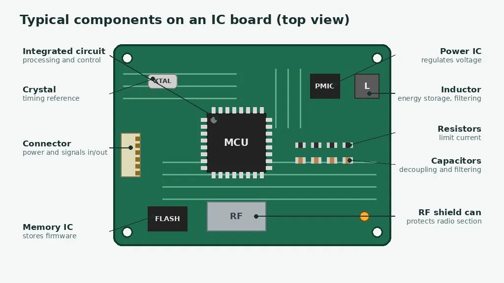
Following the power through a board
The easiest way to learn what is on a board is to follow the electricity. Power arrives at a connector, passes through protection and regulation, feeds the chips, and the chips talk to everything else. Every stage has its own family of parts, and every family has its own way of letting you down.
Start at the connector. It might be a barrel jack, a USB-C port or a screw terminal, and it is the one part that people physically yank on. That is why connectors often keep through-hole anchor pins even on an otherwise all-surface-mount board. They are also tall, heavy and slow to rework, and their footprints are where mistakes in a CAD library show up first. Check the pitch, the orientation and the shield tabs against the manufacturer drawing, not against the last project's footprint.
Right behind the connector sit the parts nobody photographs: a fuse or resettable fuse, a diode or MOSFET that blocks reversed polarity, and a transient voltage suppressor that soaks up static discharge and surges. They cost pennies compared with the chips behind them. A board that skips them tends to learn the lesson the first time somebody plugs in the wrong adapter.
Next comes regulation. A switching converter chops the input voltage and uses an inductor and capacitors to turn it into a lower, steadier rail. A linear regulator is simpler and quieter, but it burns the difference as heat. The inductor deserves a close look at two numbers, saturation current and DC resistance, because an undersized one runs hot and wastes the efficiency you chose the converter for. The capacitors need the same suspicion. Small ceramic capacitors can lose a big share of their rated value when a DC voltage sits across them, so a part printed with 10 microfarads may deliver far less on a 12 volt rail.
Then the processor or microcontroller. Its datasheet will ask for small ceramic capacitors right beside each power pin. These decoupling capacitors act as tiny local reservoirs that supply the sharp current spikes the chip draws every time it switches, and they only work if they sit close. Nearby you will usually find memory for the firmware and a crystal that provides the clock. Crystals are fussy. The load capacitance has to match what the crystal expects, and a mismatch can produce a board that boots on the bench and refuses to start in a cold room. It is a strange fate for one of the cheapest parts on the list.
Resistors are scattered everywhere. Pull-ups and pull-downs hold lines at a known level, dividers set reference voltages, and small series resistors calm fast signal edges or limit current through an LED. A one percent tolerance is a sensible default around analog circuits, while five percent is fine for a pull-up. Watch the power rating as well, since a resistor running near its limit gets hot and drifts.
Small diodes, transistors and LEDs fill in the rest of the analog neighborhood. A Schottky diode drops less voltage than an ordinary one and is the usual choice in power paths. A small MOSFET switches a load on and off under the control of a logic pin, and a bipolar transistor still turns up where a cheap, simple amplifier is enough. LEDs look trivial, yet they are one of the few parts a customer will stare at every day, so brightness, color consistency between batches and the exact resistor feeding them are worth specifying properly.
Beyond that, the board might carry interface chips for USB, Ethernet or CAN, motor drivers, sensors and converters. Each of them arrives with a recommended support circuit in its datasheet. Copying that circuit closely is the cheapest insurance a designer can buy.
Active versus passive, in one paragraph
Engineers sort parts into active and passive groups, and the split is worth a minute. Active parts, such as transistors and integrated circuits, can control current or amplify a signal, and they need a supply to do it. Passive parts, such as resistors, capacitors and inductors, cannot amplify anything. Resistors turn energy into heat, while capacitors and inductors hold energy for a moment and give it back, but none of them can add energy to the circuit. That is why a capacitor counts as passive even though it stores charge. For buyers the practical lesson is simple: the active parts tend to be expensive and scarce, and the passive parts tend to be cheap and numerous, so they need different kinds of attention.
Reading the parts list like an assembler
Every part on a board carries a reference designator, a short label that ties the schematic, the layout and the bill of materials together. By convention R is a resistor, C a capacitor, L an inductor, D a diode, Q a transistor, U an integrated circuit, Y a crystal and J a connector. So U3 on the silkscreen is the third chip in the design, and the row for C14 in the parts list tells the assembler which value and package belongs at that spot.
Good parts-list hygiene saves hours. Put identical parts on one line with all their designators, keep the manufacturer part numbers unambiguous, and mark anything that should stay empty, often called do-not-populate. When the parts list, the schematic and the placement file all agree, the assembler can start without a single clarification email. When they disagree, the build stops while someone decides which document is right, and that someone is usually busy.
Packages: where smaller stops being clever
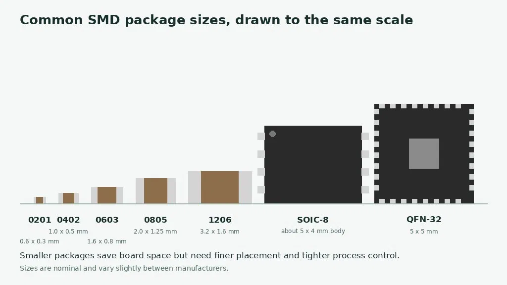
A package is the physical body of a part, and it decides how much space the part takes, how it gets soldered and how easily anyone can inspect it. Chip resistors and capacitors are named by size codes. A 0603 measures about 1.6 by 0.8 millimeters, a 0402 about 1.0 by 0.5, and a 0201 about 0.6 by 0.3, which is small enough to lose on a workbench and hard enough to place that it demands a tightly controlled line.
Chips come in their own families. Leaded packages such as SOIC are easy to look at, because you can see every joint. A QFN has no leads at all, only pads on the underside and a large thermal pad in the middle, so the joints are hidden and the paste printing has to be right. A BGA moves every connection under the body, which is wonderful for density and means the joints can only be checked with X-ray.
Through-hole parts have not gone away. Big connectors, transformers and large electrolytic capacitors still benefit from leads that pass through the board and anchor mechanically. A sensible rule is to use the largest package your layout can afford. Small packages save area, but they make prototyping, rework and repair harder, and the area you save rarely pays for the trouble.
What the reflow oven does to your choices
Most of a modern board is assembled by surface mount machines. Solder paste is printed through a stencil, a placement machine drops each part onto its pads, and the board rides through an oven whose temperature profile melts the solder in a controlled sequence. Automated optical inspection then checks for missing, shifted or reversed parts.
Several part choices show up in that process. If the pads on the two ends of a small resistor are unequal, surface tension can lift one end during melting, a defect called tombstoning. Moisture-sensitive chips must be stored and baked according to their rating, because trapped moisture can crack a package when the oven heats it. Hidden joints under BGAs and QFNs need X-ray. Most products today also use lead-free solder, which melts at a higher temperature than the old tin-lead alloys, so every part has to be rated for the peak temperature the oven reaches. None of this is exotic, but a design that ignores it will produce yield problems that look mysterious later.
Why prototypes lie
A prototype built on a bench is a flattering witness. Someone orders one or two of everything from whichever stock is nearest, solders the awkward parts by hand and swaps in a close substitute when something is out of stock. The board works, the demo goes well, and the design is declared ready.
Production then asks different questions. Can that part be bought by the thousand? Is the substitute that rescued the prototype now written into the parts list, or only into somebody's memory? Does the package that was easy to solder by hand suit a placement machine, and does the stencil need a different opening for it? The gap between a working prototype and a repeatable build is mostly made of components. Closing it means freezing the parts list, recording the real part numbers that worked, and running a small pilot batch through the real process before committing to volume. A pilot costs a fraction of what a failed volume run does.
Radio and fast signals punish sloppiness
Boards carrying wireless or high-speed signals are less forgiving than ordinary control boards. Trace width and the distance to the ground plane set the impedance, so the layer stack and laminate have to match what the designer calculated. Decoupling capacitors belong right at the pins, radio paths should be short and direct, and metal shield cans keep the radio section away from digital noise.
The parts change too. A filter built with ordinary capacitors can detune because their value shifts with temperature and voltage, so radio circuits usually call for stable dielectrics and inductors with a high quality factor. Footprint errors that would be harmless on a slow board can ruin an antenna match. If your product has a radio, ask for a manufacturability review of the layout before the first order, not after the first failure.
Choosing parts without regretting it
When you choose IC board components, the electrical specification is the easy part. Voltage, current, tolerance and power rating are all printed in the datasheet, and the rule is to leave margin rather than run at the limit. A capacitor rated for twice the working voltage and a resistor that dissipates half its rating will outlive their tight cousins by a wide gap, and they cost almost nothing extra.
The next question is the footprint. The pad pattern in your layout must match the drawing in the datasheet of the exact part you intend to buy, not a part that looks similar. Then check the temperature grade. Commercial, industrial and automotive parts cover different ranges, and the grade you need depends on where the product will really live, which may be a hot enclosure rather than a living room.
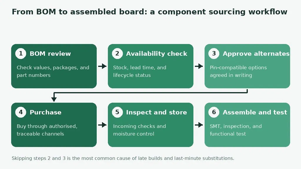
After that comes the question that gets asked too late: can you buy it next year? Look at stock, lead time and whether the maker has announced that the part is nearing end of life. For generic passives, approve a pin-compatible alternative in advance so a shortage does not stop the line. If the product needs safety, medical or automotive certification, choose parts that support it from the start.
Finally, write the bill of materials as if a stranger will read it, because one will. Every line needs the manufacturer, the full manufacturer part number, the reference designators, the quantity and the package. A line that says only "10k resistor" forces the buyer to guess the size, tolerance and power rating, and guesses turn into wrong parts.
Buying them: shortages, fakes and some boring habits
Even carefully chosen IC board components can cause delays if they cannot be bought on time. Shortages and long lead times hit popular microcontrollers and power chips hardest. Counterfeit and re-marked parts are a real risk when parts come from unverified channels, and end-of-life notices have a habit of arriving in the middle of a product's life. Storage mistakes can ruin moisture-sensitive parts before they ever reach the machine.
The remedy is a set of boring habits, done in the right order. Review the bill of materials first, check availability and lifecycle second, and get alternates approved before you need them. Buy through authorised and traceable channels, inspect parts when they arrive, and store reels and trays properly until they are used. The cheap checks come early because that is when a problem is still cheap to fix.
Counterfeits rarely announce themselves. Warning signs include prices well below the market, mixed date codes inside a single reel, surface markings that look sanded or reprinted, and packaging that has been opened and resealed. Buying only from authorised channels is the real defence, and incoming inspection catches what slips through anyway.
You also have to decide who buys the parts. In a turnkey arrangement the manufacturer sources everything, which saves time and draws on their purchasing relationships. In a consigned arrangement you supply some or all of the parts, which gives you control and also makes you responsible for quantity, quality and arrival date. Many projects mix the two. Whichever you choose, order a small overage of cheap passives, since placement machines lose a few parts in every run.
Reel quantities and minimum orders are the other piece of arithmetic people forget. Passives are sold on reels of thousands, and a part used four times per board may cost less to buy as a full reel than as a cut piece of tape with a handling fee. Chips often carry a minimum order too. Ask for both prices before assuming the cheaper unit price is cheaper overall, and keep leftover reels labeled and sealed, since they are the first thing you will want when the next batch comes around.
Mistakes that keep repeating
The most common failed first build starts with a wrong footprint, a pad pattern that does not match the real package. Close behind is polarity: diodes, electrolytic capacitors and chips all carry orientation marks that must agree with the silkscreen, and a reversed part is hard to spot once the board is in a box.
Missing or distant decoupling capacitors cause resets and noise problems that appear only at full speed, which is the worst moment to meet them. Power chips with exposed thermal pads need enough copper and correctly sized stencil openings to shed heat, and a pad that is poorly soldered can make a perfectly good chip run hot. Relying on a single supplier or a single part number for everything leaves no room for a shortage. And because components are rarely killed by one big stress, derating is cheap insurance: run parts well inside their limits and keep hot parts away from heat-sensitive ones such as electrolytic capacitors and crystals.
Finally, test the board before anyone ships it. Incoming checks confirm part numbers and date codes, optical inspection finds visible defects, and in-circuit or flying probe testing measures individual nets and values. A functional test then runs the board the way a customer will use it. A wrong resistor found at incoming inspection costs minutes. The same error found in a customer's hands can cost a recall.