A Trustworthy PCB and Electronic Manufacturing Enterprise! Contact Us



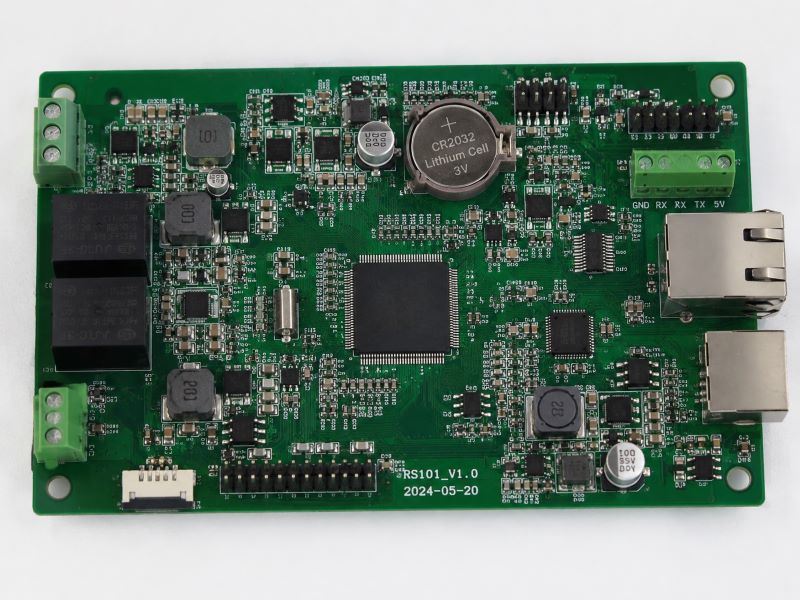
Industrial control hardware often has to work quietly in the background for years. A rs101 circuit board used in this type of equipment may not look particularly complex from the outside, but its internal PCB design can determine whether the system remains stable under electrical noise, temperature changes, vibration, and continuous operation. For PCB engineers and procurement teams specializing in high-frequency and industrial control applications, designing this hardware is rarely about achieving the smallest possible size; it is about ensuring that the system can handle electrical loads, protect sensitive signals from switching noise, maintain power distribution stability, and survive hundreds of thousands of operating cycles.
Understanding the Role of an Industrial Control PCB
Industrial control systems are built around a simple principle: receive information, process it, and generate an appropriate response. A controller may receive signals from temperature sensors, pressure sensors, encoders, switches, cameras, or other machines, and then evaluate the information to send commands to motors, valves, actuators, displays, communication modules, or power devices. The rs101 circuit board connects all of these functions, typically housing microcontrollers, memory devices, analog-to-digital converters, communication interfaces like Ethernet, RS-232, RS-485, and CAN, alongside relays, MOSFETs, DC/DC converters, and protection components.
The challenge is that these circuits do not all behave in the same way. A communication interface requires clean differential routing, a relay generates significant transients when switching, a switching regulator introduces high-frequency noise, and an analog sensor input requires a quiet electrical environment. Putting all of these functions onto one board requires careful planning.
Start With the Electrical Architecture and Power Supply Design
Before placing components, engineers should divide the design into functional zones: power input, power conversion, digital processing, analog sensing, communication, output control, and protection. This helps map out where current flows and where noise is generated. A stable power system is the foundation of any industrial control board, as many field failures that initially appear to be software problems actually originate from unstable power rails, excessive ripple, transient voltage, or poor grounding.
Depending on the application, engineers must incorporate robust input protection strategies—such as fuse protection, reverse-polarity protection, TVS diodes, overvoltage/overcurrent protection, and EMI filtering—to defend against long-cable effects and industrial surges. When utilizing switching regulators for multi-voltage rails, the layout of the high-current switching loop must be kept as small as practical. Long traces in high-current switching loops increase parasitic inductance, create additional EMI, and lead to disappointing real-world performance despite an excellent regulator IC choice.
Grounding, Signal Integrity, and High-Frequency Layout
Ground design is frequently oversimplified, but simply pouring copper everywhere does not automatically solve noise problems. Engineers need to track current return paths, recognizing that high-frequency current follows the path of lowest impedance rather than the shortest visible path. Maintaining continuous reference planes, separating noisy power areas, and properly distinguishing between signal ground, power ground, protective earth, and chassis connections are critical.
Modern industrial controllers increasingly incorporate high-speed interfaces like Ethernet, USB, and LVDS, which demand rigorous high-frequency PCB practices:Controlled Impedance: Routing logic signals and switching frequencies where controlled impedance traces prevent signal reflections.Low-Loss Dielectrics: Utilizing high-frequency laminates with stable dielectric constants and low dissipation factors to ensure minimal insertion loss.Thermal Via Integration: Dissipating localized heat generated by high-density power distribution away from microcontrollers and relays.Differential Pair Geometry: Maintaining consistent trace width and spacing without abrupt changes to protect signal integrity.
Managing Analog Signals, Relays, and Thermal Stress
Industrial systems frequently process small analog inputs for temperature, pressure, or vibration alongside noisy relays, solenoids, and motor drivers that create severe voltage spikes during switching. Flyback diodes, TVS devices, RC snubbers, and varistors must be positioned directly adjacent to the switching elements to suppress these transients effectively.
Furthermore, continuous operation inside sealed enclosures requires proactive thermal management. Copper spreading areas, thermal vias, and a clear understanding of component power dissipation prevent premature hardware degradation. The selected stack-up—whether a 4-layer, 6-layer, or 8-layer configuration—must be coordinated with the manufacturer to align dielectric thickness, copper weight, and impedance tolerances before production.
EMC, DFM, and Manufacturing Quality Assurance
EMI control must begin during PCB design rather than after a failed compliance test. Reducing current loop areas, keeping high-noise nodes compact, maintaining continuous reference planes, and protecting external interface connectors ensure the system withstands harsh industrial electromagnetic environments.
Design for Manufacturability (DFM) must be integrated early. Reviewing trace widths, spacing, hole diameters, copper balance, and solder mask clearances prevents production bottlenecks. Selecting the appropriate surface finish—such as ENIG for fine-pitch components or HASL for cost-sensitive builds—directly impacts assembly yield and long-term reliability. Ultimately, prioritizing strict quality control standards, IPC compliance, and full traceability for laminate materials guarantees that the rs101 circuit board delivers the high reliability required for demanding industrial applications.