A Trustworthy PCB and Electronic Manufacturing Enterprise! Contact Us



PCB diodes commonly used in PCBs (printed circuit boards) are mainly divided into rectification, voltage regulation, switching, protection, and light-emitting types. They utilize the unidirectional conductivity or special breakdown characteristics of PN junctions to achieve current control, voltage regulation, and circuit protection.
Common Diode Types
Rectifier Diode: The forward voltage is 0.7V, which is the standard for power supplies. It is most commonly used for AC to DC conversion and general rectification. It is very robust and reliable for high current.
Zener Diode: When reverse biased, it can achieve very precise voltage regulation. It is widely used in power supplies and voltage reference circuits. The voltage rating ranges from 2V to 200V.
Schottky Diode: Check the symbol marking: Schottky pcb diodes generally have a symbol marked on the surface, with a triangular arrow symbol indicating the positive pole, and the other end being the negative pole.
Diode color dot: In the case of point-contact Schottky diodes, there is usually a polarizing color dot (white or red), with the end marked with the colored dot being the positive pole, and the other end being the negative pole.
Photodiode: For photodiodes packaged in a metal housing, there is a bump underneath the metal. The pin closest to the bump is the positive pole, and the other end is the negative pole.
Diode color dot: The pin marked with a colored dot is the positive pole, and the other pin is the negative pole. Photodiodes have two different leads, with the long lead being the positive pole and the short lead being the negative pole. For rectangular photodiodes, markings are often made to indicate that the direction of the light-receiving surface is the positive pole, and the other direction is the negative pole.
LED (Light Emitting Diode): LEDs are relatively common, and the positive and negative poles are easy to distinguish. The long lead is the positive pole, and the short lead is the negative pole. When the leads are the same, the very small metal piece inside the LED tube is the positive pole, and the large piece is the negative pole. For SMD LEDs, there is generally a small bump to distinguish the positive and negative poles, with a special mark indicating the negative pole, and no special mark indicating the positive pole.
Varactor Diode: The end of the varactor diode coated with a black mark is the negative pole, and the other end is the positive pole. For varactor diodes with yellow and red rings coated on both ends of the tube shell, the end with the red ring is the positive pole, and the end with the yellow ring is the negative pole.
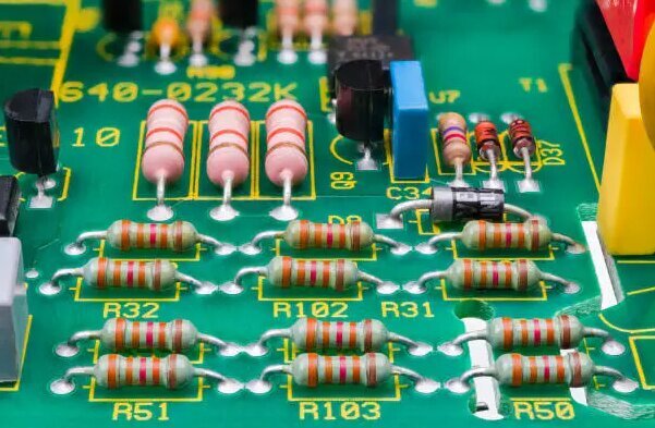
PCB diodes
How to Identify the Positive and Negative Poles of Diodes on a Circuit Board?
Correctly identifying the positive and negative poles of diodes is key to ensuring normal circuit operation and subsequent troubleshooting. Several practical identification methods are introduced below.
First, the most intuitive way is to observe the marking on the diode body. Most diodes have polarity marks printed on the surface, such as black or gray rings, vertical lines, diagonal lines, and some also have arrow symbols. These marks are usually located on the negative pole side of the diode, that is, the N-type material end. As long as you find this mark, you can determine that the corresponding side is the negative pole, and the other end is naturally the positive pole.
Second, for new diodes with uncut leads, you can also distinguish them by lead length. Generally speaking, the positive lead is longer than the negative lead. This is because the positive pole needs to be connected to the positive terminal of the power supply, and the slightly longer lead facilitates soldering and wiring.
If the above two methods are difficult to judge, such as when the markings are blurred or the leads have been cut flat, you can also use a multimeter for measurement. Set the multimeter to the diode test gear, and touch the red and black probes to the two ends of the diode respectively. If the screen displays a forward voltage drop value, usually around a few tenths of a volt, then the probe connected to the red probe is the positive pole, and the probe connected to the black probe is the negative pole. If it displays infinity, it means the probes are connected in reverse; swap them and measure again.
It should be noted that if the diode has already been soldered onto the circuit board and surrounded by other components such as resistors and capacitors, the appearance markings may be blocked, and the measurement results may also be interfered with. In this case, the most reliable method is to consult the circuit diagram to confirm the polarity.
In summary, identifying the positive and negative poles of diodes is not complicated. By observing markings, distinguishing lead lengths, or using a multimeter for measurement, you can basically determine them quickly and accurately. Mastering these methods not only helps to correctly install diodes, but also helps to detect potential problems such as reverse connection and short circuits in a timely manner. We hope the above introduction is helpful to you.
Different Application Fields of PCB Diodes
In essence, PCB Diodes greatly assist various applications in modern electronic products and even electronic projects. Therefore, we would like to share its different roles in application fields.
Correction: Since diodes can convert AC to DC, they are commonly used in rectifiers and power supplies. In addition, different current productions will cause its characteristics to change continuously. Therefore, diodes can keep the current stable under power fluctuations. The ability of diodes to allow only one current to flow is another characteristic. Therefore, rectification is related to the fact that when AC flows through the control in one direction, the diode prevents current from flowing in the other direction.
Radio Wave Detection: Once the receiver of the radio receives the signal, its route turns to the diode. Therefore, the signal will flow in a single channel; then, in the circuit, it can eventually generate energy. In addition, the signal it receives can be changed with the help of sound waves.
Voltage Control: Since diodes can be switched to the circuit, they can manage the voltage entering and leaving the device; bistable diodes are usually deployed in this case.
Current Conversion: Generally, current conversion is often associated with rectifiers because they can convert current from AC to DC through rectifier circuits. It can detect the voltage and current entering the system and convert them into what they should be.
PCB diodes are important components in modern electronic products. They control current, regulate voltage, and protect circuits from damage. Understanding different types of diodes, such as signal diodes, power diodes, Zener diodes, and Schottky diodes, helps ensure efficient circuit design. The role of PCB diodes in power conversion and voltage regulation is crucial for maintaining device performance.