A Trustworthy PCB and Electronic Manufacturing Enterprise! Contact Us



With the rapid development of new energy vehicles, industrial power supplies, energy storage systems, communication equipment, and high-power electronic products, the importance of high current PCB design has become increasingly prominent. Compared to standard PCBs, high-current PCBs must handle larger currents, higher power densities, and more complex thermal management requirements; therefore, the design and manufacturing processes require a strong focus on issues such as trace width, copper thickness, heat dissipation capabilities, current distribution, and EMC.
What is a High-Current PCB?
A high-current PCB typically refers to a printed circuit board capable of carrying heavy current loads. Generally, when the current flowing through a PCB exceeds 5A—or even 10A—specific high-current design considerations become critical. In certain industrial equipment, power supply modules, motor drives, and new energy vehicle Battery Management Systems (BMS), currents can reach tens or even hundreds of amperes.
The core objectives of high-current PCB design are:
Reducing heat generation in traces
Minimizing voltage drop
Enhancing reliability
Preventing copper foil burnout
Improving long-term stability
Consequently, designing a high-current PCB is not merely a matter of "widening the traces"; rather, it involves a comprehensive engineering approach encompassing materials, structural design, thermal management, and manufacturing processes.
Key Considerations for High-Current PCB Design
1. Increasing Copper Thickness
The most direct method for boosting a PCB's current-carrying capacity is to increase the copper thickness.
Common copper thicknesses include:
1 oz (35 μm)
2 oz (70 μm)
3 oz (105 μm)
4 oz and above
For high-current applications, a copper thickness of 2 oz or greater is typically recommended.
Advantages of Thick-Copper PCBs:
Lower electrical resistance
Reduced voltage drop
Enhanced heat dissipation capabilities
Higher reliability
However, thick-copper PCBs also increase manufacturing complexity, imposing stricter requirements on trace precision and etching capabilities.
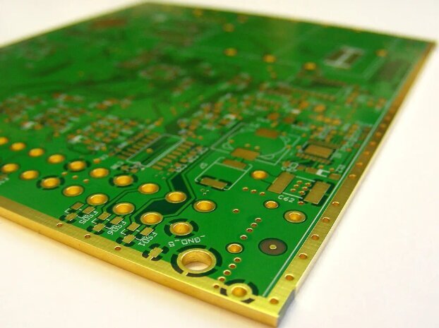
high current PCB design
2. Widening Traces
When designing high-current PCBs, one of the most critical factors to consider is the minimum width of the traces. So, what constitutes the minimum trace width for high-current applications? Simply put, this depends on the current load, copper thickness, and allowable temperature rise limits. However, as a general rule—based on standard copper thicknesses (e.g., 1 oz/ft²)—traces carrying high currents typically require a width of 0.5 mm or more for every 1 to 2 amperes of current. This ensures safety, reliability, and effective thermal management.
In PCB design, the width of a trace directly impacts its ability to carry current without overheating or failing. For high-current applications—such as power supplies, automotive electronics, or industrial systems—narrow traces can lead to excessive heat buildup, voltage drops, or even board failure. Determining the correct minimum trace width to accommodate the required current capacity is essential for preventing these issues and ensuring long-term reliability.
Traces that are too thin for the current they carry will experience a temperature rise due to electrical resistance. If this temperature exceeds safe limits, it can damage components, degrade the PCB substrate material, or cause delamination. By calculating the appropriate trace width, you can effectively manage thermal loads and maintain the integrity of your design.
3. Thermal Management Design
Component Layout Optimization: High-current and heat-generating components (such as MOSFETs, voltage regulators, and large inductors) should not be placed in close proximity to one another. Positioning high-heat components near the center of the board allows heat to dissipate evenly in all directions; conversely, placing them near the edges can easily lead to localized heat accumulation.
Thermal Vias: A dense array of thermal vias should be placed beneath the pads of heat-generating components to conduct heat from the top layer down to large copper pour areas on the bottom layer, or to an external heatsink.
Specialized Substrates: For extremely high-power heat sources, consider utilizing Metal-Core PCBs (MCPCBs) or ceramic substrates to achieve superior thermal conductivity.
4. Material Selection for High Current PCBs
The choice of material for a PCB is critically important. It must be robust, durable, and capable of withstanding high temperatures.
Optimal Materials for High Current PCBs
FR-4: This is the most common material. It is cost-effective and suitable for most applications; however, for very high-current scenarios, you may require something more robust.
Metal Core: This material offers excellent thermal dissipation properties. It is frequently used in LED applications where heat generation is a significant concern.
High-Temperature FR-4: Similar to standard FR-4, but capable of withstanding higher operating temperatures. This is an excellent choice if your PCB will be exposed to substantial heat.
Common Mistakes to Avoid in High Current PCB Design
Even experienced designers can make mistakes when working with high current PCBs. The following are some common pitfalls to watch out for when determining trace width and managing thermal performance:
1. Underestimating Current Load
If trace width is calculated based on average current rather than peak current, overheating may occur during periods of high demand. Always design for the maximum anticipated current to ensure safety.
2. Neglecting Environmental Conditions
The ambient temperature and airflow surrounding a PCB can significantly impact heat dissipation. If your board operates in a hot or enclosed environment, you may require wider traces or additional cooling measures to maintain safe operating temperatures.
3. Overlooking Voltage Drop
In high-current traces, electrical resistance can lead to a significant voltage drop over long distances. This can compromise performance, particularly within power supply circuits. Wider traces or shorter routing paths can help minimize this issue.
High current PCB design is not merely a matter of system performance; it directly impacts product reliability and safety. Designers must comprehensively consider a multitude of factors—including copper thickness, trace width, thermal management, current distribution, and EMC—to ensure a robust and safe design.