A Trustworthy PCB and Electronic Manufacturing Enterprise! Contact Us



A treadmill PCB board isn't one component — it's three functionally distinct boards working together: the main control board, the drive board (motor control board), and the display board, none of which are interchangeable. This treadmill circuit board guide covers how each board works, how to narrow a fault to the right subsystem, and what actually matters when sourcing a replacement.
Board Types and Core Functions
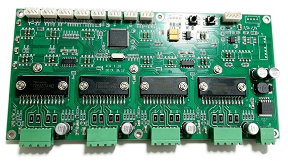
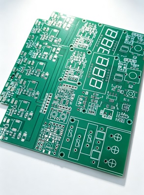
The main control board handles user interaction, button input, and system coordination. The treadmill motor control board takes commands from the main board and uses PWM to regulate output voltage and current, driving the motor while handling real-time protection against overvoltage, overcurrent, overheating, and stall — it's the power core of the system. The display board handles data output and button input.
You can narrow a fault down from symptoms alone: display and buttons work but the belt won't start → drive board. No power at all, dead screen → power input or main control board. Glitchy display or unresponsive buttons → usually a ribbon cable or display board issue.
Hardware and Working Principle
The power supply section converts AC mains into DC rails — typically 5V for logic and 12V for drivers, relays, and cooling fans. Key components here (rectifier bridge, fuse, high-voltage capacitors, switching controller) are also the most common failure points — aging capacitors or unstable low-voltage output can cause seemingly unrelated symptoms elsewhere in the unit.
The control/firmware section is built around a microcontroller that processes button commands, safety-key signals, and sensor feedback, then generates motor drive commands and manages fault codes. Firmware compatibility matters enormously for any treadmill PCB board replacement: two boards can share identical dimensions and connectors while running different firmware, and installing a visually identical but functionally mismatched board can cause incorrect speed control or missing features.
Common Faults and Diagnostic Steps
1. No response, dead screen: Check the power cord, plug, breaker, and fuse, then measure the 310V high-voltage rail and 5V/12V rails. No low-voltage output points to a failed power IC or capacitor; normal output points to firmware or the main chip.
2. Display works but belt won't move: Usually a drive-board power fault — check the safety key and motor wiring, then measure drive voltage at the motor terminals. Voltage present but no rotation suggests worn brushes; no voltage points to a burnt power device or drive IC.
3. Speed fluctuates under load: Clean and recalibrate the speed sensor (0.5–1.2mm flywheel gap), check whether the 5V rail dips under acceleration, and check the current-sense resistor for drift.
4.Shuts down with a fault code: Usually overcurrent, overload, or overheat protection. Rule out mechanical resistance first, then motor faults, then thermal performance.
5.Smoke or repeated fuse blows: A serious short-circuit fault — cut power immediately and don't power-cycle or upsize the fuse to "test through" it.
Key Parameters for Replacement and Selection
How to choose a treadmill PCB board comes down to matching electrical, mechanical, communication, and functional requirements — not just board size and connector layout.
1. Motor specifications: Confirm DC vs. AC motor, rated voltage, continuous power, peak current, and brushed/brushless design. The replacement's power-handling capability must meet or exceed the original.
2. Power and drive architecture: Check input voltage, PWM control method, and regenerative braking support — different drive topologies aren't interchangeable even with matching connectors.
3. Connectors and protocol: Verify pin assignments, baud rate, and safety-key/e-stop logic. The most reliable match comes from comparing PCB part number, model, revision, and firmware version — batches within the same brand can differ.
4. Hardware and functional configuration: Power semiconductor ratings should meet the original spec; confirm firmware supports required features (incline, heart-rate, Bluetooth) — a board can be electrically fine but functionally incomplete.
5. Universal replacement boards: These need configuration (motor power, voltage, protection thresholds) and calibration testing before use — never power on with default parameters.
Installation, Testing, and Maintenance
Fully disconnect power and wait 10+ minutes for capacitor discharge before installation; photograph original wiring first. Test in three stages: power-on with no motor/belt connected, then unloaded motor operation, then light-load belt operation — don't skip any stage. For maintenance, keep the unit dry and ventilated, clean the speed sensor and flywheel every 50 hours, avoid prolonged full-load runs, and keep the cooling path clear. At the first sign of unusual noise, smell, or smoke, cut power immediately and diagnose before repairing.
Conclusion
A treadmill PCB board integrates power conversion, PWM motor control, sensor feedback, and safety protection into one specialized system — with the power stage, supply, and sensing circuits mattering most for reliability. When selecting a replacement, never rely on size or connector appearance alone: motor specs, drive architecture, communication interfaces, and firmware version all need verification. For manufacturers and engineering teams, understanding these parameters is what it takes to build a reliable treadmill motor control board that lasts.