A Trustworthy PCB and Electronic Manufacturing Enterprise! Contact Us



In modern electronics, amplifier PCBs play a crucial role in processing and boosting signals. Whether you are building an audio system, communication equipment, or a power control unit, understanding the fundamentals of amplifier PCBs is essential.
What is an amplifier PCB?
An amplifier PCB is a printed circuit board specifically designed to support and interconnect components used to amplify electrical signals. These boards provide the foundation for circuits that boost voltage, current, or power—commonly used in audio systems, wireless transmitters, and industrial equipment. Unlike general-purpose PCBs, amplifier boards are optimized for signal gain, low noise, and stable performance under varying electrical loads.
There are various types of amplifier PCBs, designed according to specific applications and functions. Below are some types commonly found in many electronic products:
Power Amplifier PCB. A power amplifier PCB is an electronic board designed to increase the power level of an input signal. An audio power amplifier PCB is a prime example; it is used when you want to output a microphone signal through speakers. In this scenario, the power amplifier PCB must deliver high current, which benefits both signal amplification and audio filtering.
Microwave Power Amplifier PCB. This type of amplifier PCB is used to boost and amplify microwave signals, enabling more efficient transmission and higher fidelity over long distances. The power required for transmission from a base station depends on the distance between microwave antennas. When designing a microwave power amplifier PCB, it is critical to carefully select the appropriate transistors and conduct tests to evaluate actual performance.
Audio Amplifier PCB. For tech enthusiasts with a passion for music, audio amplifiers are likely a familiar device. Audio amplifier PCBs enhance sound quality and increase volume. These PCBs can be categorized into Class A, B, C, and D; Class A is the simplest type but has the lowest efficiency, while Class D offers the highest efficiency with virtually zero output power loss.
Operational Amplifier (Op-Amp) PCB. An operational amplifier PCB is a device capable of performing specific "operations"—such as summation, integration, differentiation, and filtering—on a signal to modify the input. Op-amp PCBs are better suited for low-output-power devices, such as headphones.
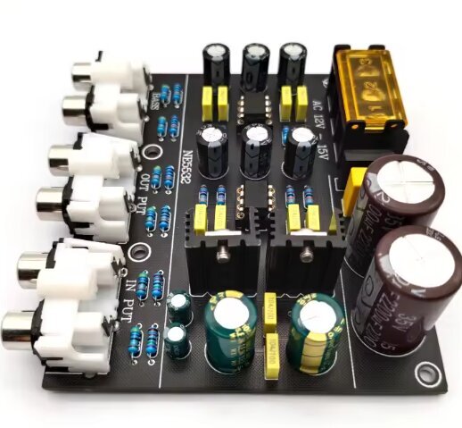
Amplifier PCB
Key Characteristics of Amplifier PCBs
A high-quality amplifier PCB requires a balance across multiple dimensions. Its core characteristics include:
1. Signal Integrity
The essence of an amplifier is "faithful amplification"—meaning the output signal should retain the original characteristics of the input signal as much as possible, with only its magnitude increased. This necessitates a PCB design that minimizes signal distortion, noise, and interference. Poor layout choices can lead to parasitic capacitance, leakage currents, or voltage fluctuations, all of which compromise amplification performance.
2. Thermal Management
During operation, power transistors and output stages generate significant heat. Class A amplifiers, in particular, have an efficiency of only about 20–30%, with the majority of energy dissipated as heat. Inadequate heat dissipation not only destabilizes circuit performance but also shortens component lifespan. Consequently, effective thermal management is critical to the success of an amplifier PCB.
3. Compactness and Reliability
Amplifier PCBs typically utilize Surface Mount Technology (SMD) to achieve a compact design. Simultaneously, they must operate reliably over the long term, consistently delivering stable performance. The design process requires balancing multiple constraints, including physical dimensions, signal flow, and mechanical strength.
Key Performance Indicators for Amplifiers
Core metrics for evaluating amplifier performance include gain, bandwidth, efficiency, and distortion:
Gain: The ratio of output signal amplitude to input signal amplitude. It is categorized into voltage gain (Av=uo/ui), current gain (Ai=io/ii), and power gain (Ap=Po/Pi), and is commonly expressed in decibels (dB)—for example, voltage gain Av(dB)=20lg|Av|.
Bandwidth: The frequency range over which the amplifier provides effective amplification. It is usually defined by the frequency interval where gain drops by 3 dB, reflecting the amplifier's ability to handle signals of varying frequencies.
Efficiency: The ratio of output power to the DC power supplied by the power source. This is a critical focus for power amplifiers to minimize energy loss and heat generation.
Distortion: The difference in waveform between the output and input signals. This includes linear distortion (frequency distortion) and non-linear distortion (harmonic distortion) and serves as a key metric for assessing signal fidelity.
Amplifier PCB design integrates insights from circuit theory, materials science, and engineering practice. It requires both a profound understanding of fundamental electrical principles—such as Ohm's Law and electromagnetic field propagation—and meticulous attention to practical layout details, including trace widths, component spacing, and thermal management.
Driven by the ever-growing demand for wireless communication and high-fidelity audio, amplifier PCBs are evolving toward higher frequencies, greater integration, and more rigorous thermal management. Whether for Hi-Fi enthusiasts seeking ultimate sound quality or engineers developing next-generation communication equipment, mastering the core design principles of amplifier PCBs is essential for creating high-performance products.