A Trustworthy PCB and PCBA Manufacturing Enterprise! Contact Us


")
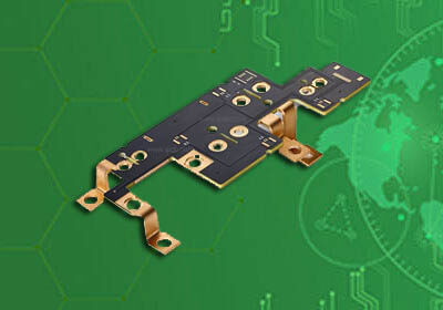
Product: LTCC (low temperature co-fired ceramic)
Dimensions: 100 mm × 100 mm
Minimum line width/line spacing: min.0.075mm/0.15mm
Aperture: min.0.1mm
Accuracy: ±0.2%
Layer: ≤40 layers
Product application: Substrate for automotive circuit modules
LTCC ceramic substrate technology uses new ceramic materials and microwave thick film integration technology to realize three-dimensional integration technology of complex microwave and digital circuits. With the rapid development of monolithic integration technology, the integration level of active devices is getting higher and higher, reaching an unprecedented level, which makes the integration of passive devices very important. LTCC technology can meet the integration needs of passive components such as resistors, capacitors, inductors, filters, and couplers.
The resistances of the LTCC ceramic substrate are 10 Ω, 100 Ω, 1K Ω and 10K Ω respectively. The accuracy of the surface resistance adjustment method is less than 1%, and the accuracy of the embedded resistance is less than 30%. Other passive components can be designed according to relevant material parameters. The LTCC substrate can be wired in multiple layers, up to 40 layers.
")
Low temperature co-fired ceramic PCB (LTCC PCB)
In recent years, ceramic substrate technology has developed rapidly. Especially on the basis of traditional ceramic substrates, high-temperature co-fired ceramic substrates and low-temperature CO fired ceramic substrates have been developed, allowing ceramic substrates to be used more deeply and in high-density assembly for high-power circuits. Wider application. Low-temperature co-fired multilayer substrate is a newly developed micro-assembly substrate that combines the advantages of thick film technology and high-temperature co-fired. Over the past decade, this substrate has developed rapidly. As a high-density, high-speed circuit board, it is widely used in computers, communications, missiles, rockets, radar and other fields. For example, DuPont in the United States used an 8-layer low-temperature co-fired multilayer substrate in the test circuit of the Stinger missile. Japan's Fuji General has used 61-layer low-temperature co-fired ceramic substrates to produce the multi-chip modules of the vp2000 series supercomputers, while NEC has produced 78-layer low-temperature co-fired multi-layer substrates with an area of 225 × 225 square millimeters. It contains 11,540 I/O terminals and can install up to 100 VLSI chips.
Low-temperature co-fired multilayer ceramic substrates are composed of many individual ceramic substrates. Each ceramic substrate consists of a layer of ceramic material and a conductive circuit attached to the ceramic layer, often called a conductive strip. The vias of the ceramic layer are filled with conductive material. It connects conductive strip lines in different ceramic layers to form a three-dimensional circuit network. The IC chip is mounted on the top layer of multilayer ceramic. The integrated block is soldered to the circuit in the multi-layer ceramic substrate through pins to form an interconnection circuit. The metal conductive layer on the surface of the substrate is preformed during the sintering process of the ceramic substrate, and there are needle-shaped terminals on the bottom of the substrate. In this way, co-fired multilayer ceramic substrates are used to assemble microcomponents to form a high-density, high-speed, and high-reliability three-dimensional structure.

Typical structure of LTCC ceramic PCB
From the perspective of chemical composition, currently used ceramic materials that can achieve low-temperature sintering mainly include crystallized glass systems, glass + ceramic composite systems and amorphous glass systems. Among them, crystallized glass systems and glass + ceramic composite systems are the most popular ones in recent years. The focus of research has been the development of (Mg, Ca) TiO3 series, BaO- TiO2 series, ZnO- TiO2 series, BaN-Nd2O3- TiO2 series, (Zr, Sn) TiO3 series, (Zn, Sn) TiO3 series, ( There are many LTCC material systems such as Ba, Nb) TiO3 series and borosilicate series.
LTCC PCB has many advantages compared to other PCB technologies
1. Ceramic materials have excellent characteristics such as high frequency, high-speed transmission, and wide passband. The dielectric constant of LTCC materials can vary over a wide range depending on the composition. Using metal materials with high conductivity as conductor materials can improve the quality factor of the circuit system and increase the flexibility of circuit design;
2. It can adapt to the requirements of high current and high temperature resistance, and has better thermal conductivity than ordinary PCB circuit boards. Significantly optimizes the heat dissipation design of electronic equipment, with high reliability, can be used in harsh environments, and extends service life;
3. High-level circuit boards can be made, multiple passive components can be embedded, and the cost of packaging components can be avoided. On high-level three-dimensional circuit boards, passive and active integration can be achieved, which is beneficial to increasing the assembly density of circuits and further reducing volume and weight;
4. It has good compatibility with other multi-layer wiring technologies. For example, the combination of LTCC and thin-film wiring technology can achieve higher assembly density and better performance of hybrid multi-layer substrates and hybrid multi-chip modules;
5. The discontinuous production process facilitates quality inspection of each layer of wiring and interconnect holes before making finished products, which is conducive to improving the yield and quality of multi-layer substrates, shortening the production cycle, and reducing costs.
6. Energy saving, material saving, greenness and environmental protection have become an irresistible trend in the development of the parts industry. LTCC also caters to this development need, minimizing the environmental pollution of raw materials, waste and production processes.
LTCC products have a wide range of applications, such as mobile phones of various standards, Bluetooth modules, GPS, PDA, digital cameras, WLAN, automotive electronics, optical disc players, etc. Among them, mobile phone usage accounts for the main part, accounting for more than 80%; followed by Bluetooth modules and WLAN. Due to the high reliability of LTCC products, their applications in automotive electronics are also increasing. LTCC products used in mobile phones include LC filters, duplexers, functional modules, transceiver switch functional modules, balanced-unbalanced converters, couplers, power dividers, common mode chokes, etc.
The purpose of using LTCC technology in SMD is to increase assembly density, reduce volume, reduce weight, add new functions, improve reliability and efficiency, and shorten the assembly cycle. Voltage controlled oscillator (VCO) is a key component of mobile communication equipment. VCO can be produced through LTCC technology to meet the requirements of mobile communication for small size, lightweight, low power consumption, and low phase noise (high C/N ratio) . Internationally, LTCC technology has been applied to make high-performance surface-mounted VCOs, and a series of products has been formed. The volume of VCOs has been greatly reduced by using LTCC technology. From 1996 to 2000, the volume of VCO decreased by more than 90%. The volume of this surface-mounted VCO is only 1/5-1/20 of the volume of the original VCO with leads. The new VCO produced using LTCC technology has the advantages of small size, low power consumption, good high-frequency characteristics, small phase noise, and suitable for surface mounting, and has been widely used in the field of mobile communications. This kind of miniaturized VCO is widely used in digital communication system terminals such as GSM, DCS, CDMA, and PDC, as well as satellite communication-related terminals such as the Global Positioning System (GPS).
The rapid development of mobile communications has further promoted the miniaturization of DC/DC converters, providing a broad application market for SMD DC/DC converters. Many foreign power supply manufacturers are using LTCC technology to actively develop standard SMD DC/DC converters with rated power of 5-30W and various universal input and output voltages. Some new DC/DC converter designs also offer shorter start-up times. In addition, LTCC technology has also been used to produce chip multi-layer antennas, Bluetooth components, radio frequency amplification voltage-controlled attenuators, power amplifiers, phase shifters and other surface-mounted devices for mobile communications.
LTCC modules have received great attention and are widely used in military and aerospace equipment due to their compact structure and strong resistance to mechanical shock and thermal shock. Its application in automotive electronics will be very extensive in the future.
Product: LTCC (low temperature co-fired ceramic)
Dimensions: 100 mm × 100 mm
Minimum line width/line spacing: min.0.075mm/0.15mm
Aperture: min.0.1mm
Accuracy: ±0.2%
Layer: ≤40 layers
Product application: Substrate for automotive circuit modules
iPCB Circuit provides support for PCB design, PCB technology, and PCBA assembly. You can request technical consultation or quotation for PCB and PCBA here, please contact email: sales@ipcb.com
We will respond very quickly.