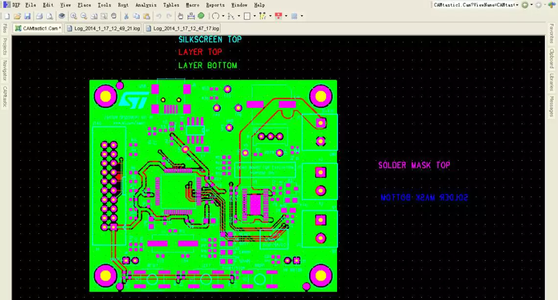
PCB circuit board production of engineering files used, PCB files, ODB++ files, Gerber including EXCELLON. Production to do board files Gerber used to light drawing out of the film, used for exposure, screen printing, EXCELLON format files is the drilling, milling program files, used for drilling and moulding. PCB files need to be converted to Gerber and EXCELLON in order to be provided to the production use, ODB++ file PCB factory production use of CAM software can be read directly into the ODB++ file data.
What is PCB file?
PCB file refers to the design file saved after the EDA software design, this file can not be directly used as a tool file for the production process. Production equipment does not recognise the PCB file format, so all PCB data files saved in the EDA design file need to be converted to the Gerber file format for production use. The file format used by the production equipment is Gerber format, some inspection equipment can use ODB++ file format.
Suffixes of PCB files
Various PCB software design PCB file format is not the same, an EDA software can only open its own design file, the suffix of this file is not the same, with the suffix to distinguish the PCB file to determine the file design of the PCB design software.
brd is Cadence Allegro, Eagle.
max is Cadence's other PCB design software ORCAD.
.min is the text file output from ORCAD.
.pcbdoc for Altium Designer
.asc is the text format of some PCB software, e.g. PADS, protel, P-cad, etc.
.dat, .neu, .net and so on. Netrual files generated by Mentor
.cam. files from CAM350 or Camtastic 2000
ODB++ format files generated by EDA software.
PCB design software such as PADS, Protel, KiCad.

PCB design software
Excellon File Introduction and Usage
EXCELLON was the first to use computerised drills and gong machines, it developed a set of instructions for computer controlled machines called EXCELLON Computer Numeric Control, some of which have become industry standards. In 1979 EXCELLON updated the FormatTwo language to combine the drill and causeway commands into a common language system - so that pre-1979 models called Generation One could only use Format One, while post-1979 models called Generation Two could use Format One. The pre-1979 models known as Generation One could only use Format One, while the post-1979 models known as Generation Two could use either the Format One or Format Two language system.
ODB++ Transfer Data Files
What is ODB++?
The ODB++ file is an ASCII, bi-directional transfer file proposed by Mentor (IPC member). The file integrates all PCB and circuit board assembly functional descriptions. Covers PCB design, manufacturing and assembly requirements. Includes all PCB drawings, wiring layers, wiring diagrams, pad stacking, fixtures and all other information. It is mainly used to replace the insufficiency of GERBER file, which contains more manufacturing and assembly information.
Advantages of ODB++ files
The original goal of the ODB format was to satisfy the need for the data from the design file to be eventually classified as a product, initially used by PCB manufacturers, thus eliminating the need to collect CAM files in multiple formats - such as Gerber, Excellon, IPC-356 and even IPC-350, all of which were used in the design process. Gerber, Excellon, IPC-356, and even IPC-350, were early industry attempts to simplify the conversion process. The key to the success of the ODB format is that it is recognised by the industry.
Gerber/Excellon
What is Gerber file?
Gerber files, also known as "light painting", usually represents only one format such as RS-274, 274D, 274X, etc., which acts as a two-way medium to convert the designed graphic data into PCB manufacturing, i.e., a CAD-CAM data conversion format specification. Important use is the PCB format staff to draw, and finally by the PCB manufacturer to complete the PCB manufacturing. The mainstream GERBER format in the manufacturing industry is GERBER 274X.
Gerber File Usage
If you want to perform PCB manufacturing, you must use Gerber file in the whole process, such as online Gerber file view, PCB drawing printing, production data creation, online AOI, etc. Gerber file is similar to a guide star, which can help PCB manufacturing smoothly in the whole process.
When dealing with PCB assembly, Gerber contains a template layer that provides the basis for adjusting the position of various electronic components, providing guidelines for SMT and through-hole assembly processes.
Common RS-274X Gerber files defects
Separate physical files for each layer of PCB information (e.g., copper layer images, manufacturing records, assembly layers, etc.).
No legal layer stacking - must communicate with the manufacturer about the form of the drawing, file name, and text.
No drill information included - must send "N.C. Drill" files separately, often deviating from the drill locations in the gerber.
Does not contain any electrical connection information (network meter), requires a separate network meter to be sent for electrical bare board testing - most likely does not match the gerber file.
Does not contain any component layout or BOM information - must generate a separate pick-and-place file and procurement file. This can lead to product delays and problems for vendors who also do PCB board manufacturing and PCBA assembly.